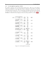


6.9 Setting the Event/Deviation Modes (A or B)
51
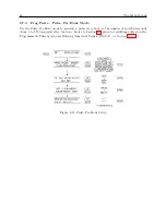
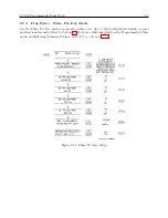
6.9.1
Arming the Event Input
When using J3 or J4, note that the event function continually arms itself for the next event until
the buffer is full. When using the RS-232C port as the input, you must arm the event function for
each event from the front panel or by using the AR command. To arm the Event Input from the
front panel see Figure 6.18 below.
Figure 6.18: Arming the Event Mode From Front Panel
Содержание 1088A
Страница 4: ...iv ...
Страница 6: ...vi ...
Страница 18: ...xviii LIST OF FIGURES ...
Страница 23: ...1 4 Attaching Rack Mount Ears to 1088A B Series Clocks 3 Figure 1 2 Attaching Rack Mount Ears ...
Страница 24: ...4 Unpacking the Clock ...
Страница 32: ...12 Front and Rear Panels ...
Страница 38: ...18 Connecting Inlet Power Input and Output Signals ...
Страница 41: ...4 1 GPS Antenna Installation 21 Figure 4 2 Antenna Mounting Bracket Figure 4 3 Antenna Mounting with AS0044600 ...
Страница 46: ...26 GPS Antenna and Cable Information ...
Страница 48: ...28 Setting Internal Jumpers Figure 5 1 Model 1088B Main Board ...
Страница 76: ...56 The Setup Menus ...
Страница 112: ...92 Serial Communication and Command Set ...
Страница 127: ...B 4 Physical Dimensions 107 Figure B 1 Suggested Mounting of the AS0094500 Surge Arrester ...
Страница 128: ...108 Using Surge Arresters ...
Страница 137: ...C 5 Option 04 Parallel BCD Output 117 C 5 2 Option 04 Firmware Setup Figure C 2 Option 04 Firmware Setup ...
Страница 145: ...C 5 Option 04 Parallel BCD Output 125 Figure C 4 Option 04 Output Jumper Settings ...
Страница 146: ...126 Options List Figure C 5 Option 04 Board Layout and Jumper Locations ...
Страница 165: ...C 12 Option 17 Parallel BCD Output and Second RS 232 Port 145 Figure C 11 Option 17 Output Jumper Settings ...
Страница 166: ...146 Options List Figure C 12 Option 17 Board Layout and Jumper Locations ...
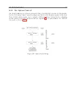
Страница 176: ...156 Options List C 14 5 Typical Network Configuration Figure C 15 Option 18 Network Configuration ...
Страница 187: ...C 16 Option 20A Four Fiber Optic Outputs 167 Figure C 22 Option 20A Jumper Locations ...
Страница 194: ...174 Options List Figure C 24 Option 23 Internal Jumper Setup ...
Страница 196: ...176 Options List Figure C 25 Option 27 Jumper Locations ...
Страница 214: ...194 Options List Figure C 28 Option 29 Connector Signal Locations ...
Страница 270: ...250 Options List ...