


172
Options List
C.17.10
Changing Hardware Settings via Internal Jumpers
It is necessary to set a jumper in order to assign the output signal to a specific I/O connector. The
following paragraphs describe the procedure for setting these jumpers.
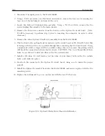
Cover Removal
To change the I/O configuration of the rear-panel connectors, the top cover of the instrument must
be removed. Turn off the instrument, and disconnect the power cord. Using a T-25 driver, remove
the four screws holding the cover (and rack mount ears, if used) in place, and lift the cover off.
WARNING:
DO NOT REMOVE top cover while power is applied.
Hazardous voltages are
present while the power cord is connected. Always disconnect the unit from the input power source
before removal of the top cover.
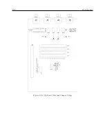
The Option 23 Comtrade Board is illustrated in Figure C.24, which shows the location of all the
jumpers along with a brief description.
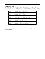
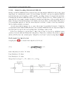
Output Function Selection
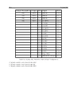
Jumpers JMP1, JMP2, JMP3, and JMP4 determine the output signals which can be made available
at I/O connectors J2, J3, J4, and J5, respectively. Figure C.24 illustrates the relationship between
these jumpers and the I/O connectors. The first step in setting an I/O channel for a specific
output signal is to move the associated jumper to the location corresponding to the desired signal.
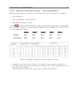
Table C.9 lists the jumper settings required for various signals.
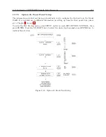
Output Mode Selection
The next step in configuring the I/O connectors is to determine whether the assigned signal is an
analog output or a digital output. This selection is accomplished by setting jumpers JMP5, JMP6,
JMP7, and JMP8 to the appropriate positions. These jumpers correspond to connectors J2, J3,
J4, and J5, respectively (see Figure C.24). If the I/O channel is to be used as a digital output, the
corresponding jumper should be set to position “A”. If the I/O channel is to be used as an analog
output, the jumper should be set to position “C”. Table C.9 lists jumper positions for individual
output signals.
Содержание 1088A
Страница 4: ...iv ...
Страница 6: ...vi ...
Страница 18: ...xviii LIST OF FIGURES ...
Страница 23: ...1 4 Attaching Rack Mount Ears to 1088A B Series Clocks 3 Figure 1 2 Attaching Rack Mount Ears ...
Страница 24: ...4 Unpacking the Clock ...
Страница 32: ...12 Front and Rear Panels ...
Страница 38: ...18 Connecting Inlet Power Input and Output Signals ...
Страница 41: ...4 1 GPS Antenna Installation 21 Figure 4 2 Antenna Mounting Bracket Figure 4 3 Antenna Mounting with AS0044600 ...
Страница 46: ...26 GPS Antenna and Cable Information ...
Страница 48: ...28 Setting Internal Jumpers Figure 5 1 Model 1088B Main Board ...
Страница 76: ...56 The Setup Menus ...
Страница 112: ...92 Serial Communication and Command Set ...
Страница 127: ...B 4 Physical Dimensions 107 Figure B 1 Suggested Mounting of the AS0094500 Surge Arrester ...
Страница 128: ...108 Using Surge Arresters ...
Страница 137: ...C 5 Option 04 Parallel BCD Output 117 C 5 2 Option 04 Firmware Setup Figure C 2 Option 04 Firmware Setup ...
Страница 145: ...C 5 Option 04 Parallel BCD Output 125 Figure C 4 Option 04 Output Jumper Settings ...
Страница 146: ...126 Options List Figure C 5 Option 04 Board Layout and Jumper Locations ...
Страница 165: ...C 12 Option 17 Parallel BCD Output and Second RS 232 Port 145 Figure C 11 Option 17 Output Jumper Settings ...
Страница 166: ...146 Options List Figure C 12 Option 17 Board Layout and Jumper Locations ...
Страница 176: ...156 Options List C 14 5 Typical Network Configuration Figure C 15 Option 18 Network Configuration ...
Страница 187: ...C 16 Option 20A Four Fiber Optic Outputs 167 Figure C 22 Option 20A Jumper Locations ...
Страница 194: ...174 Options List Figure C 24 Option 23 Internal Jumper Setup ...
Страница 196: ...176 Options List Figure C 25 Option 27 Jumper Locations ...
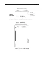
Страница 214: ...194 Options List Figure C 28 Option 29 Connector Signal Locations ...
Страница 270: ...250 Options List ...