220
Options List
NTP Authentication
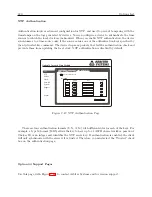
Authentication involves advanced configuration for NTP, and used to prevent tampering with the
timestamps on the logs generated by devices. You can configure a device to authenticate the time
sources to which the local clock is synchronized. When you enable NTP authentication, the device
synchronizes to a time source only if the source carries one of the authentication keys specified by
the ntp trusted-key command. The device drops any packets that fail the authentication check and
prevents them from updating the local clock. NTP authentication is disabled by default.
Option 34 Network Time Module
Status
Configure
NTP
PTP
SNMP
Clock
Network
System
Support
Logout
Authentication
Apply
Reset
M
Enable Authentication
M
M
M
M
Key Table
ID Format Key Trusted
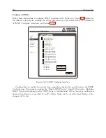
Figure C.47: NTP Authentication Page
There are four authentication formats (S, N, A, M) with different rules for each of the keys. For
example, a type M format (MD5) allows the key to have up to 31 ASCII characters like a password.
The key ID is an integer and identifies the NTP server key. If authentication is enabled, the client
will only synchronize with the server if it is trusted. Therefore, you must select the “Trusted” check
box on the authentication page.
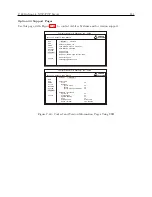
Option 34 Support Pages
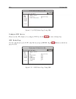
Use this page, with Figure C.48, to contact Arbiter Systems and for version support.
Содержание 1088A
Страница 4: ...iv ...
Страница 6: ...vi ...
Страница 18: ...xviii LIST OF FIGURES ...
Страница 23: ...1 4 Attaching Rack Mount Ears to 1088A B Series Clocks 3 Figure 1 2 Attaching Rack Mount Ears ...
Страница 24: ...4 Unpacking the Clock ...
Страница 32: ...12 Front and Rear Panels ...
Страница 38: ...18 Connecting Inlet Power Input and Output Signals ...
Страница 41: ...4 1 GPS Antenna Installation 21 Figure 4 2 Antenna Mounting Bracket Figure 4 3 Antenna Mounting with AS0044600 ...
Страница 46: ...26 GPS Antenna and Cable Information ...
Страница 48: ...28 Setting Internal Jumpers Figure 5 1 Model 1088B Main Board ...
Страница 76: ...56 The Setup Menus ...
Страница 112: ...92 Serial Communication and Command Set ...
Страница 127: ...B 4 Physical Dimensions 107 Figure B 1 Suggested Mounting of the AS0094500 Surge Arrester ...
Страница 128: ...108 Using Surge Arresters ...
Страница 137: ...C 5 Option 04 Parallel BCD Output 117 C 5 2 Option 04 Firmware Setup Figure C 2 Option 04 Firmware Setup ...
Страница 145: ...C 5 Option 04 Parallel BCD Output 125 Figure C 4 Option 04 Output Jumper Settings ...
Страница 146: ...126 Options List Figure C 5 Option 04 Board Layout and Jumper Locations ...
Страница 165: ...C 12 Option 17 Parallel BCD Output and Second RS 232 Port 145 Figure C 11 Option 17 Output Jumper Settings ...
Страница 166: ...146 Options List Figure C 12 Option 17 Board Layout and Jumper Locations ...
Страница 176: ...156 Options List C 14 5 Typical Network Configuration Figure C 15 Option 18 Network Configuration ...
Страница 187: ...C 16 Option 20A Four Fiber Optic Outputs 167 Figure C 22 Option 20A Jumper Locations ...
Страница 194: ...174 Options List Figure C 24 Option 23 Internal Jumper Setup ...
Страница 196: ...176 Options List Figure C 25 Option 27 Jumper Locations ...
Страница 214: ...194 Options List Figure C 28 Option 29 Connector Signal Locations ...
Страница 270: ...250 Options List ...


