9.2 Command Set
87
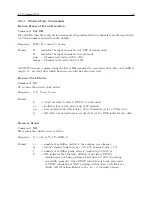
NOTE: The DL, DU, TL and TU command formats are identified as follows:
yyyy
= year
hh
= hour
mmm
= month (JAN DEC)
mm
= minute
dd
= day of month
ss
= second
ddd
= day of year
9.2.10
Programmable Pulse Output Commands
Pulse Width
Command:
nnn.nnPW
nnn.nnPW configures the Programmable Pulse output pulse width in seconds, from 0.01 to 600
seconds, in Seconds per Pulse, Pulse per Hour and Pulse per Day modes.
Response:
C
Format: nnn.nn
(0.01 to 600 seconds in 10-millisecond increments).
For values greater than 1, use a decimal point and enter trailing zeros as applicable.
Examples:
1 = 0.01 second
10 = 0.10 second
1.00 = 1 second
100 = 1 second
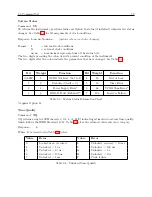
Seconds Per Pulse / Pulse Per Hour
Command:
m,nPS
m,nPS configures the programmable pulse as “Seconds per Pulse” or “Pulse Per Hour” mode as
follows:
Response:
C
Format:
m = 0, seconds–per–pulse mode
m = 1, pulse–per–hour mode
n = 1 – 60000 seconds if seconds–per–pulse mode
n = 1 – 3599 seconds offset from hour if pulse–per–hour mode
For the Seconds–Per–Pulse mode, the first pulse will be on time at the top of the minute. If n is
divisible by 60, the first pulse will be on time at the top of the hour.
For the Pulse–Per–Hour mode, the pulse will be on time at the second after the hour described by
n. For example, 1,1200ps would cause a pulse at exactly 20 minutes after the hour.
If only one number is present then the number sets the seconds as in seconds–per–pulse mode.
Содержание 1088A
Страница 4: ...iv ...
Страница 6: ...vi ...
Страница 18: ...xviii LIST OF FIGURES ...
Страница 23: ...1 4 Attaching Rack Mount Ears to 1088A B Series Clocks 3 Figure 1 2 Attaching Rack Mount Ears ...
Страница 24: ...4 Unpacking the Clock ...
Страница 32: ...12 Front and Rear Panels ...
Страница 38: ...18 Connecting Inlet Power Input and Output Signals ...
Страница 41: ...4 1 GPS Antenna Installation 21 Figure 4 2 Antenna Mounting Bracket Figure 4 3 Antenna Mounting with AS0044600 ...
Страница 46: ...26 GPS Antenna and Cable Information ...
Страница 48: ...28 Setting Internal Jumpers Figure 5 1 Model 1088B Main Board ...
Страница 76: ...56 The Setup Menus ...
Страница 112: ...92 Serial Communication and Command Set ...
Страница 127: ...B 4 Physical Dimensions 107 Figure B 1 Suggested Mounting of the AS0094500 Surge Arrester ...
Страница 128: ...108 Using Surge Arresters ...
Страница 137: ...C 5 Option 04 Parallel BCD Output 117 C 5 2 Option 04 Firmware Setup Figure C 2 Option 04 Firmware Setup ...
Страница 145: ...C 5 Option 04 Parallel BCD Output 125 Figure C 4 Option 04 Output Jumper Settings ...
Страница 146: ...126 Options List Figure C 5 Option 04 Board Layout and Jumper Locations ...
Страница 165: ...C 12 Option 17 Parallel BCD Output and Second RS 232 Port 145 Figure C 11 Option 17 Output Jumper Settings ...
Страница 166: ...146 Options List Figure C 12 Option 17 Board Layout and Jumper Locations ...
Страница 176: ...156 Options List C 14 5 Typical Network Configuration Figure C 15 Option 18 Network Configuration ...
Страница 187: ...C 16 Option 20A Four Fiber Optic Outputs 167 Figure C 22 Option 20A Jumper Locations ...
Страница 194: ...174 Options List Figure C 24 Option 23 Internal Jumper Setup ...
Страница 196: ...176 Options List Figure C 25 Option 27 Jumper Locations ...
Страница 214: ...194 Options List Figure C 28 Option 29 Connector Signal Locations ...
Страница 270: ...250 Options List ...


