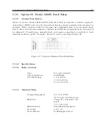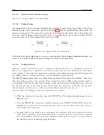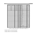
164
Options List
1. Disconnect the input power to the Model 1088B.
2. Using a T-25 torx driver (or a flat-blade screwdriver), remove the four screws securing the
top cover of the instrument, and remove the cover.
3. Locate the Option 19 terminal strip assembly. Using a T-10 torx driver, remove the two
screws holding the assembly to the main chassis.
4. Remove the three-wire connector from the header on the Option 19 circuit board. (Note:
It will be necessary to perform step 3 prior to removing the connector, in order to allow
clearance.)
5. Remove the entire Option 19 fault relay assembly from the Model 1088B.
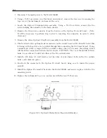
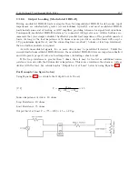
6. The location for the optional resistor is shown on the circuit board as R1. Directly below this
lettering on the board is a via (a plated-through hole connecting the two board layers). Using
a number 60 (.040) or larger drill bit, carefully enlarge the via to remove the plating, which
will break the connection between the two layers. CAUTION: The via is the middle of three
holes; be careful not to drill out either of the two outside holes.
7. Install a 100 ohm, 0.5 watt resistor (or the value of your choice) between the two outside
holes, and solder into place.
8. Re-attach the connector to the Option 19 circuit board, using care to insure the proper
polarity.
9. Install the Option 19 assembly back into the Model 1088B, and secure in place with the two
mounting screws.
10. Replace the instrument top cover, and secure with the four T-25 screws.
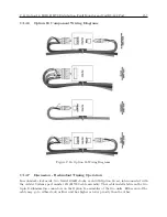
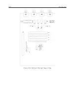
Figure C.21: Option 19 Relay Relay Board with Resistor
Содержание 1088A
Страница 4: ...iv ...
Страница 6: ...vi ...
Страница 18: ...xviii LIST OF FIGURES ...
Страница 23: ...1 4 Attaching Rack Mount Ears to 1088A B Series Clocks 3 Figure 1 2 Attaching Rack Mount Ears ...
Страница 24: ...4 Unpacking the Clock ...
Страница 32: ...12 Front and Rear Panels ...
Страница 38: ...18 Connecting Inlet Power Input and Output Signals ...
Страница 41: ...4 1 GPS Antenna Installation 21 Figure 4 2 Antenna Mounting Bracket Figure 4 3 Antenna Mounting with AS0044600 ...
Страница 46: ...26 GPS Antenna and Cable Information ...
Страница 48: ...28 Setting Internal Jumpers Figure 5 1 Model 1088B Main Board ...
Страница 76: ...56 The Setup Menus ...
Страница 112: ...92 Serial Communication and Command Set ...
Страница 127: ...B 4 Physical Dimensions 107 Figure B 1 Suggested Mounting of the AS0094500 Surge Arrester ...
Страница 128: ...108 Using Surge Arresters ...
Страница 137: ...C 5 Option 04 Parallel BCD Output 117 C 5 2 Option 04 Firmware Setup Figure C 2 Option 04 Firmware Setup ...
Страница 145: ...C 5 Option 04 Parallel BCD Output 125 Figure C 4 Option 04 Output Jumper Settings ...
Страница 146: ...126 Options List Figure C 5 Option 04 Board Layout and Jumper Locations ...
Страница 165: ...C 12 Option 17 Parallel BCD Output and Second RS 232 Port 145 Figure C 11 Option 17 Output Jumper Settings ...
Страница 166: ...146 Options List Figure C 12 Option 17 Board Layout and Jumper Locations ...
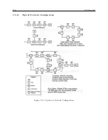
Страница 176: ...156 Options List C 14 5 Typical Network Configuration Figure C 15 Option 18 Network Configuration ...
Страница 187: ...C 16 Option 20A Four Fiber Optic Outputs 167 Figure C 22 Option 20A Jumper Locations ...
Страница 194: ...174 Options List Figure C 24 Option 23 Internal Jumper Setup ...
Страница 196: ...176 Options List Figure C 25 Option 27 Jumper Locations ...
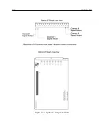
Страница 214: ...194 Options List Figure C 28 Option 29 Connector Signal Locations ...
Страница 270: ...250 Options List ...


