C.21 Option 32/33: NTP Server – Obsoleted by Opt34
199
c)
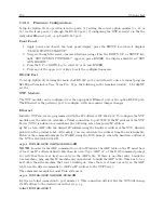
Open a telnet connection to port 9999 and set all required parameters.
telnet 192.168.0.232 9999
NOTE:
The temporary IP address is reverted after every power reset of the NTS. Be sure to enter
the configuration and store the parameters to make the changes permanent.
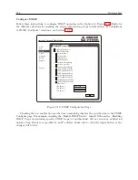
After making a connection to configure the NTP server (either through the Ethernet or RS-232
port), the screen should display the top four lines; to enter the Setup Mode, you must press Enter
on the terminal (pc).
*** NTS ***
MAC address 00204AAB5F03
Software version V5.8.13.RC2 (050126) CPK 580 M100
Press Enter to go into Setup Mode
*** basic parameters
Hardware:
Ethernet TPI
IP addr 192.168.0.232, no gateway set
*** Security
SNMP is
enabled
SNTP Community Name:
public
Telnet Setup is
enabled
TFTP Download is
enabled
Port 77FEh is
enabled
ECHO is
enabled
*** NTS parameters
Antenna Type:
GPS/Arbiter
SNTP Ref.Identifier:
‘‘gps2"
Encryption is disabled
Sending UDP datagram to Port 024C(hex) every 000 minutes
Send UDP datagram to:
Change Setup:
0 Basic configuration
1 NTS configuration
6 Security
7 Factory defaults
8 Exit without save
9 save and exit
Your choice ?
Serial
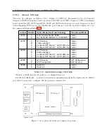
An ASCII terminal or PC with a terminal emulation can be connected to the option RS-232 port,
but JMP2 and JMP3 must be set to “C” (for Ethernet Port 1) or “D” (for Ethernet Port2), and
JMP4 set to “B”. The terminal (or PC) should be configured to 9600 Baud, 8 data-bits, 1- stop
bit, no parity. The power must be cycled to enter the configuration mode. The self-test begins
after power-up. About a half-second later the Error (red) LED starts blinking. Now send three
Содержание 1088A
Страница 4: ...iv ...
Страница 6: ...vi ...
Страница 18: ...xviii LIST OF FIGURES ...
Страница 23: ...1 4 Attaching Rack Mount Ears to 1088A B Series Clocks 3 Figure 1 2 Attaching Rack Mount Ears ...
Страница 24: ...4 Unpacking the Clock ...
Страница 32: ...12 Front and Rear Panels ...
Страница 38: ...18 Connecting Inlet Power Input and Output Signals ...
Страница 41: ...4 1 GPS Antenna Installation 21 Figure 4 2 Antenna Mounting Bracket Figure 4 3 Antenna Mounting with AS0044600 ...
Страница 46: ...26 GPS Antenna and Cable Information ...
Страница 48: ...28 Setting Internal Jumpers Figure 5 1 Model 1088B Main Board ...
Страница 76: ...56 The Setup Menus ...
Страница 112: ...92 Serial Communication and Command Set ...
Страница 127: ...B 4 Physical Dimensions 107 Figure B 1 Suggested Mounting of the AS0094500 Surge Arrester ...
Страница 128: ...108 Using Surge Arresters ...
Страница 137: ...C 5 Option 04 Parallel BCD Output 117 C 5 2 Option 04 Firmware Setup Figure C 2 Option 04 Firmware Setup ...
Страница 145: ...C 5 Option 04 Parallel BCD Output 125 Figure C 4 Option 04 Output Jumper Settings ...
Страница 146: ...126 Options List Figure C 5 Option 04 Board Layout and Jumper Locations ...
Страница 165: ...C 12 Option 17 Parallel BCD Output and Second RS 232 Port 145 Figure C 11 Option 17 Output Jumper Settings ...
Страница 166: ...146 Options List Figure C 12 Option 17 Board Layout and Jumper Locations ...
Страница 176: ...156 Options List C 14 5 Typical Network Configuration Figure C 15 Option 18 Network Configuration ...
Страница 187: ...C 16 Option 20A Four Fiber Optic Outputs 167 Figure C 22 Option 20A Jumper Locations ...
Страница 194: ...174 Options List Figure C 24 Option 23 Internal Jumper Setup ...
Страница 196: ...176 Options List Figure C 25 Option 27 Jumper Locations ...
Страница 214: ...194 Options List Figure C 28 Option 29 Connector Signal Locations ...
Страница 270: ...250 Options List ...

