154
Options List
Since all of the components which pass dc current are effectively in series as far as the dc current
is concerned, the resistances can simply be summed up. If the total is less than 500 ohms, proper
operation is ensured.
The cable resistance is 43 ohms/km (13 ohms/Mft.) for the dc monitor current. The dc resistance
of the Model 10885A redundant-ring adapter is 4 ohms. The dc resistance of each Model 10884A
terminator and each Model 10883A splitter is 30 ohms. The number of taps has no effect on the
system dc resistance.
The magnitude of the dc monitor current is 10 mA +10% with a maximum dc open-circuit voltage
of 8.5 volts. In the USA, NEC class-2 wiring is acceptable.
Detection of Short Circuits; Drive Capability
The Option 18 bus output is intended to drive a total ac load of 50 ohms or greater, although it
will continue to operate without excessive signal distortion into any impedance. The bus monitor
includes a circuit which detects the presence of the IRIG-B signal at the system output. The bus
monitor is sensitive to both the waveshape of the signal at the bus output (it must look like a
modulated IRIG-B signal), and the level of that signal.
If the load impedance drops below approximately 40 ohms, a drop in signal level will occur due
to the 21-ohm source resistance of the bus driver. At this point, the output level will drop below
the threshold required by the bus monitor, in turn causing a bus FAULT to be reported. Since
in normal operation the system load exceeds 50 ohms, such a fault must be the result of a short
circuit at some point along the bus.
Thus, the bus monitor function of the Option 18 IRIG-B distribution output is capable of detecting
the three most likely types of system fault: failure of the IRIG-B drive signal at the source, an
open circuit along the distribution bus, or a short of the distribution bus.
Installation
Installation of the IRIG-B distribution bus is straightforward for those experienced with the instal-
lation of control and communication wiring. No special tools are required. All of the components
are terminated with pluggable, screw-type terminal blocks. A 3 mm (1/8”) flat-bladed screwdriver,
wire cutters and strippers are all that is required to terminate the cable.
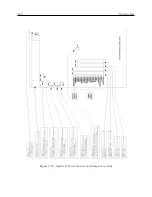
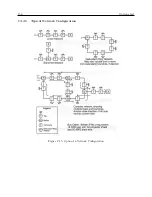
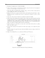
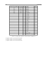
The figures which follow show typical network topologies. The various components may be con-
nected together in any configuration desired, provided that the basic rules described above are not
broken. Multiple branches or loops may be used, and the number of taps is limited only by the
loading and signal level requirements described above. The limit of 24 taps only applies if they all
are loaded with 600 ohms; for higher or lower load impedances, a greater or fewer number of taps
will be possible.
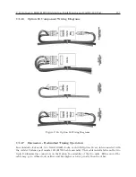
When connecting the network, observe polarity of all components. Both the IRIG-B signal and
the dc loop monitor current have polarity which must be observed for proper operation. All of the
components needed to assemble your system are marked for polarity.
The output of the taps is isolated and floating, and either end may be grounded. However, if the
signal polarity is incorrect, the device being driven by the tap may not operate properly.
Содержание 1088A
Страница 4: ...iv ...
Страница 6: ...vi ...
Страница 18: ...xviii LIST OF FIGURES ...
Страница 23: ...1 4 Attaching Rack Mount Ears to 1088A B Series Clocks 3 Figure 1 2 Attaching Rack Mount Ears ...
Страница 24: ...4 Unpacking the Clock ...
Страница 32: ...12 Front and Rear Panels ...
Страница 38: ...18 Connecting Inlet Power Input and Output Signals ...
Страница 41: ...4 1 GPS Antenna Installation 21 Figure 4 2 Antenna Mounting Bracket Figure 4 3 Antenna Mounting with AS0044600 ...
Страница 46: ...26 GPS Antenna and Cable Information ...
Страница 48: ...28 Setting Internal Jumpers Figure 5 1 Model 1088B Main Board ...
Страница 76: ...56 The Setup Menus ...
Страница 112: ...92 Serial Communication and Command Set ...
Страница 127: ...B 4 Physical Dimensions 107 Figure B 1 Suggested Mounting of the AS0094500 Surge Arrester ...
Страница 128: ...108 Using Surge Arresters ...
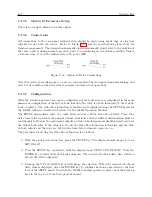
Страница 137: ...C 5 Option 04 Parallel BCD Output 117 C 5 2 Option 04 Firmware Setup Figure C 2 Option 04 Firmware Setup ...
Страница 145: ...C 5 Option 04 Parallel BCD Output 125 Figure C 4 Option 04 Output Jumper Settings ...
Страница 146: ...126 Options List Figure C 5 Option 04 Board Layout and Jumper Locations ...
Страница 165: ...C 12 Option 17 Parallel BCD Output and Second RS 232 Port 145 Figure C 11 Option 17 Output Jumper Settings ...
Страница 166: ...146 Options List Figure C 12 Option 17 Board Layout and Jumper Locations ...
Страница 176: ...156 Options List C 14 5 Typical Network Configuration Figure C 15 Option 18 Network Configuration ...
Страница 187: ...C 16 Option 20A Four Fiber Optic Outputs 167 Figure C 22 Option 20A Jumper Locations ...
Страница 194: ...174 Options List Figure C 24 Option 23 Internal Jumper Setup ...
Страница 196: ...176 Options List Figure C 25 Option 27 Jumper Locations ...
Страница 214: ...194 Options List Figure C 28 Option 29 Connector Signal Locations ...
Страница 270: ...250 Options List ...


