158
Options List
Output Signal Enable and Configuration
When jumper JMP17 on the main clock board is set properly, the digital outputs of that clock
are controlled by the redundant-control interface. The status of the drivers is indicated by the
’On Line’ LED annunciator on the clock front panel. Refer to paragraphs 3.2 through 3.3.4 of the
1088B Operation manual if it should be necessary to modify the jumper settings; they are normally
preset at the factory prior to shipment.
To make the best use of the redundant clock feature, both clocks should have their main four outputs
set for the same set of signals. Then, the outputs may be directly tied in parallel, and the ’On Line’
clock will drive the connected loads. Note that the output enable only affects the digital outputs
(everything except IRIG-B modulated and chart recorder output).
If you connect two analog
outputs together, no damage will be done, but both signals will be present simultaneously. The
IRIG bus distribution output of the Option 18 assembly should be used for a redundant modulated
IRIG-B output; it includes an on-line enable relay, which is also controlled by the output enable
function.
On-Line Control and Arbitration
In normal operation, when no fault is detected, the ’On Line’ clock is determined by the ’luck of
the draw.’ The only exception to this is if one of the clocks includes a higher-stability internal
timebase, such as Option 12. In this case, the clock with the higher-quality timebase will be the
nominal on-line clock.
Once each second, the clocks exchange status information via the RS-232 interface. In the event that
one of the clocks determines that it is not as healthy as the other, it will automatically relinquish
on-line status to the other unit. For the most part, this is performed in firmware; however, there
is also a hardware input to the redundant-control circuit, which is driven by the microprocessor
watchdog/reset generator. If this circuit detects any error, a direct hardware transfer to the other
unit is performed. Thus, in the event of a processor failure which might prevent the clock from
relinquishing on-line status via firmware, the transfer will be accomplished automatically through
this hardware feature.
Determination of the on-line clock in the event of multiple failures is made by comparison of the
status bytes (refer to paragraph 4.4 for a discussion of clock status). The clock with the lower-
valued status byte will be elected to on-line status. The status of both clocks may be monitored
from either of the clocks via the SS RS-232 command; see Appendix A of the 1088B Operation
manual for a description.
Use With Other Options
Certain other options, including Options 03 and 20, can be installed in the clock mainframe along
with the Option 18 board, and also can provide redundant control of their outputs via the redundant
clock control function of the Option 18 assembly. See the documentation for these options to
determine if any jumper settings are required to take advantage of this feature.
C.14.8
Option 18 Setup
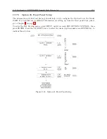
The setup menu to control the operation of the Option 18 interface is shown earlier in this section
(Option 18 Firmware Setup). No internal configuration is necessary for proper operation of the
Содержание 1088A
Страница 4: ...iv ...
Страница 6: ...vi ...
Страница 18: ...xviii LIST OF FIGURES ...
Страница 23: ...1 4 Attaching Rack Mount Ears to 1088A B Series Clocks 3 Figure 1 2 Attaching Rack Mount Ears ...
Страница 24: ...4 Unpacking the Clock ...
Страница 32: ...12 Front and Rear Panels ...
Страница 38: ...18 Connecting Inlet Power Input and Output Signals ...
Страница 41: ...4 1 GPS Antenna Installation 21 Figure 4 2 Antenna Mounting Bracket Figure 4 3 Antenna Mounting with AS0044600 ...
Страница 46: ...26 GPS Antenna and Cable Information ...
Страница 48: ...28 Setting Internal Jumpers Figure 5 1 Model 1088B Main Board ...
Страница 76: ...56 The Setup Menus ...
Страница 112: ...92 Serial Communication and Command Set ...
Страница 127: ...B 4 Physical Dimensions 107 Figure B 1 Suggested Mounting of the AS0094500 Surge Arrester ...
Страница 128: ...108 Using Surge Arresters ...
Страница 137: ...C 5 Option 04 Parallel BCD Output 117 C 5 2 Option 04 Firmware Setup Figure C 2 Option 04 Firmware Setup ...
Страница 145: ...C 5 Option 04 Parallel BCD Output 125 Figure C 4 Option 04 Output Jumper Settings ...
Страница 146: ...126 Options List Figure C 5 Option 04 Board Layout and Jumper Locations ...
Страница 165: ...C 12 Option 17 Parallel BCD Output and Second RS 232 Port 145 Figure C 11 Option 17 Output Jumper Settings ...
Страница 166: ...146 Options List Figure C 12 Option 17 Board Layout and Jumper Locations ...
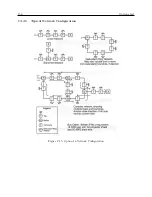
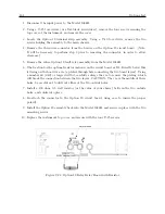
Страница 176: ...156 Options List C 14 5 Typical Network Configuration Figure C 15 Option 18 Network Configuration ...
Страница 187: ...C 16 Option 20A Four Fiber Optic Outputs 167 Figure C 22 Option 20A Jumper Locations ...
Страница 194: ...174 Options List Figure C 24 Option 23 Internal Jumper Setup ...
Страница 196: ...176 Options List Figure C 25 Option 27 Jumper Locations ...
Страница 214: ...194 Options List Figure C 28 Option 29 Connector Signal Locations ...
Страница 270: ...250 Options List ...


