198
Options List
C.21.3
Firmware Configuration.
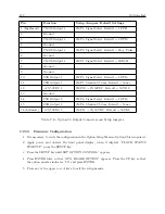
Setup for Option 32/33 operation is in two parts: (1) setting the correct option number (i.e. 32 or
33) via the front panel, or through the RS-232 port; (2) configuring the NTP server(s) via the the
individual Ethernet port, or option RS-232 port.
Front Panel
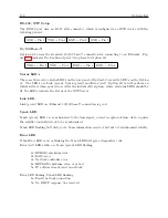
1. Apply power and observe the front panel display; press the SETUP key when it displays
“CLOCK STATUS STARTUP”.
2. Navigate through the series of menu selections, using either the DOWN, UP or SETUP key,
until “SET OPTION CONTROL?” appears; press ENTER; the display should read “SET
AUX. BOARD?”
3. Press the UP or DOWN key to select 32 or 33 and ENTER.
4. Press any of the upper row of keys to exit the configuration menu.
RS-232 Port
To set up Option 32/33 using the main clock RS-232 port, you will need to use a terminal program
like HyperTerminal or Tera Term Pro. Type the following in the terminal window, “1,8,1088XI”
set the .
NTP Module.
The NTP module can be configured over the appropriate Ethernet port or the option RS-232 port.
The Ethernet is the preferred port to configure, with no required jumper changes.
Ethernet
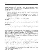
Initially, NTP servers are programmed with the IP address of 192.168.0.232. To configure the NTP
module over the network, establish a Telnet connection to port 9999. If the IP address of the NTP
Server (NTS) is unknown or undefined, the following sets a temporary IP address:
a)
Set a static ARP with the desired IP address using the hardware address of the NTS, which is
printed on the product label. Alternately, you can calculate the address from the serial number.
Below is the command example for WinXP, using the DOS prompt, when the hardware address of
the NTS is 00-20-4A-02-64-0B.
arp -s 192.168.0.232 00-20-4A-02-64-0B
NOTE:
In order for the ARP command to work in Windows, the ARP table on the PC must have
at least one IP address defined other than its own. Type “ARP A” at the DOS command prompt
to verify that there is at least one entry in the ARP table. If there is no other entry beside the
local machine, ping another IP machine on your network to build the ARP table. This has to be a
host other than the machine that you’re working on. Once there is at least one entry in the ARP
table, use the listed commands to ARP an IP address to the NTP Server.
The command example for most Unix systems is:
arp -s 192.168.0.232 00:20:4A:02:64:0B
b)
Open a telnet connection to port number 1. This connection will fail, but the NTS will change
its IP address to the desired one in that step, e.g.
telnet 192.168.0.232 1
Содержание 1088A
Страница 4: ...iv ...
Страница 6: ...vi ...
Страница 18: ...xviii LIST OF FIGURES ...
Страница 23: ...1 4 Attaching Rack Mount Ears to 1088A B Series Clocks 3 Figure 1 2 Attaching Rack Mount Ears ...
Страница 24: ...4 Unpacking the Clock ...
Страница 32: ...12 Front and Rear Panels ...
Страница 38: ...18 Connecting Inlet Power Input and Output Signals ...
Страница 41: ...4 1 GPS Antenna Installation 21 Figure 4 2 Antenna Mounting Bracket Figure 4 3 Antenna Mounting with AS0044600 ...
Страница 46: ...26 GPS Antenna and Cable Information ...
Страница 48: ...28 Setting Internal Jumpers Figure 5 1 Model 1088B Main Board ...
Страница 76: ...56 The Setup Menus ...
Страница 112: ...92 Serial Communication and Command Set ...
Страница 127: ...B 4 Physical Dimensions 107 Figure B 1 Suggested Mounting of the AS0094500 Surge Arrester ...
Страница 128: ...108 Using Surge Arresters ...
Страница 137: ...C 5 Option 04 Parallel BCD Output 117 C 5 2 Option 04 Firmware Setup Figure C 2 Option 04 Firmware Setup ...
Страница 145: ...C 5 Option 04 Parallel BCD Output 125 Figure C 4 Option 04 Output Jumper Settings ...
Страница 146: ...126 Options List Figure C 5 Option 04 Board Layout and Jumper Locations ...
Страница 165: ...C 12 Option 17 Parallel BCD Output and Second RS 232 Port 145 Figure C 11 Option 17 Output Jumper Settings ...
Страница 166: ...146 Options List Figure C 12 Option 17 Board Layout and Jumper Locations ...
Страница 176: ...156 Options List C 14 5 Typical Network Configuration Figure C 15 Option 18 Network Configuration ...
Страница 187: ...C 16 Option 20A Four Fiber Optic Outputs 167 Figure C 22 Option 20A Jumper Locations ...
Страница 194: ...174 Options List Figure C 24 Option 23 Internal Jumper Setup ...
Страница 196: ...176 Options List Figure C 25 Option 27 Jumper Locations ...
Страница 214: ...194 Options List Figure C 28 Option 29 Connector Signal Locations ...
Страница 270: ...250 Options List ...

