C.22 Option 34: NTP/PTP Server
233
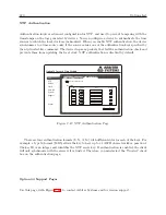
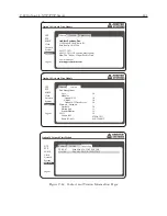
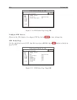
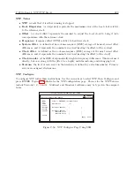
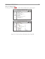
which shows that both the SNMP service and traps are enabled. To view the SNMP Status screen,
log in to the Option 34 with the web interface and select the SNMP tab on the left.
Note that SNMP configuration is available only through the web interface.
SNMP Traps
SNMP Traps (v1) or Notifications (v2) may be used to:
•
send notification of a change
•
signify a problem with the system
•
notify that some needed system maintenance was performed
•
notify that someone has logged on to the system
Traps, or notifications, are generally sent to an IP address of a computer running SNMP man-
agement software. The Option 34 can store up to three separate target IP addresses.
Enabling SNMP Service and Configuring SNMP Traps
To configure snmp, open your web browser and log in to the Option 34.
Note: SNMP cannot be
configured using the SSH Console.
Select “SNMP” on the left and “Configure” tab at the top.
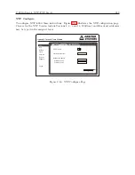
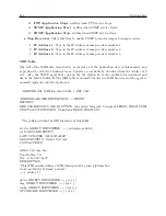
Figure C.42 illustrates a list of selection boxes to configure your snmp service and traps. At the
bottom are three boxes for IP addresses designated as trap receivers, where trap messages may be
sent.
SNMP Configuration Reference
Listed below are the configurable options available for snmp traps. Trap events will only be sent
out if the Trap Receivers are selected and identified by a valid IP address.
•
Enable SNMP Service
: Select this item to make the snmp service active.
•
Enable SNMP Traps
: Select this item to make any snmp trap active.
1.
Enable System Start
: notifies when the “System” (i.e. Option 34) starts up.
2.
Enable System Stop
: notifies when the “System” (i.e. Option 34) stops.
3.
Enable Admin Login
: notifies when someone logs in to the Option 34.
4.
Enable Admin Logout
: notifies when someone logs out from the Option 34.
5.
System Time Quality
: notifies when the time quality changes.
6.
System Time Set
: notifies when the system locks to the GPS after being turned on.
7.
System Time Change
: notifies when the clock gets adjusted at some time after being
initially set.
8.
Zero Satellites Visible
: notifies when the clock loses lock.
9.
NTP Application Start
: notifies when NTP service starts.
10.
NTP Application Stop
: notifies when NTP service stops.
11.
PTP Application Start
: notifies when PTP service starts.
Содержание 1088A
Страница 4: ...iv ...
Страница 6: ...vi ...
Страница 18: ...xviii LIST OF FIGURES ...
Страница 23: ...1 4 Attaching Rack Mount Ears to 1088A B Series Clocks 3 Figure 1 2 Attaching Rack Mount Ears ...
Страница 24: ...4 Unpacking the Clock ...
Страница 32: ...12 Front and Rear Panels ...
Страница 38: ...18 Connecting Inlet Power Input and Output Signals ...
Страница 41: ...4 1 GPS Antenna Installation 21 Figure 4 2 Antenna Mounting Bracket Figure 4 3 Antenna Mounting with AS0044600 ...
Страница 46: ...26 GPS Antenna and Cable Information ...
Страница 48: ...28 Setting Internal Jumpers Figure 5 1 Model 1088B Main Board ...
Страница 76: ...56 The Setup Menus ...
Страница 112: ...92 Serial Communication and Command Set ...
Страница 127: ...B 4 Physical Dimensions 107 Figure B 1 Suggested Mounting of the AS0094500 Surge Arrester ...
Страница 128: ...108 Using Surge Arresters ...
Страница 137: ...C 5 Option 04 Parallel BCD Output 117 C 5 2 Option 04 Firmware Setup Figure C 2 Option 04 Firmware Setup ...
Страница 145: ...C 5 Option 04 Parallel BCD Output 125 Figure C 4 Option 04 Output Jumper Settings ...
Страница 146: ...126 Options List Figure C 5 Option 04 Board Layout and Jumper Locations ...
Страница 165: ...C 12 Option 17 Parallel BCD Output and Second RS 232 Port 145 Figure C 11 Option 17 Output Jumper Settings ...
Страница 166: ...146 Options List Figure C 12 Option 17 Board Layout and Jumper Locations ...
Страница 176: ...156 Options List C 14 5 Typical Network Configuration Figure C 15 Option 18 Network Configuration ...
Страница 187: ...C 16 Option 20A Four Fiber Optic Outputs 167 Figure C 22 Option 20A Jumper Locations ...
Страница 194: ...174 Options List Figure C 24 Option 23 Internal Jumper Setup ...
Страница 196: ...176 Options List Figure C 25 Option 27 Jumper Locations ...
Страница 214: ...194 Options List Figure C 28 Option 29 Connector Signal Locations ...
Страница 270: ...250 Options List ...

