C.17 Option 23, COMTRADE Sample Rate Generator
169
C.17.4
Specifications
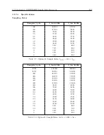
Sampling Rates
Samples/cycle
f
s
for 60 Hz
f
s
for 50 Hz
384
23040
19200
192
11520
9600
128
7680
6400
96
5760
4800
64
3840
3200
48
2880
2400
32
1920
1600
24
1440
1200
16
960
800
12
720
600
8
480
400
6
360
300
4
240
200
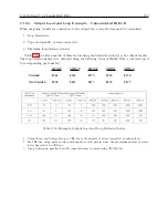
Table C.7: Option 23, Sample Rates, f
LCM
= 384
×
f
base
Samples/cycle
f
s
for 60 Hz
f
s
for 50 Hz
3200
192000
160000
1600
96000
80000
800
48000
40000
640
38400
32000
400
24000
20000
320
19200
16000
200
12000
10000
160
9600
8000
128
7680
6400
100
6000
5000
80
4800
4000
64
3840
3200
50
3000
2500
40
2400
2000
32
1920
1600
20
1200
1000
16
960
800
10
600
500
8
480
400
4
240
200
Table C.8: Option 23, Sample Rates, f
LCM
= 3200
×
f
base
Содержание 1088A
Страница 4: ...iv ...
Страница 6: ...vi ...
Страница 18: ...xviii LIST OF FIGURES ...
Страница 23: ...1 4 Attaching Rack Mount Ears to 1088A B Series Clocks 3 Figure 1 2 Attaching Rack Mount Ears ...
Страница 24: ...4 Unpacking the Clock ...
Страница 32: ...12 Front and Rear Panels ...
Страница 38: ...18 Connecting Inlet Power Input and Output Signals ...
Страница 41: ...4 1 GPS Antenna Installation 21 Figure 4 2 Antenna Mounting Bracket Figure 4 3 Antenna Mounting with AS0044600 ...
Страница 46: ...26 GPS Antenna and Cable Information ...
Страница 48: ...28 Setting Internal Jumpers Figure 5 1 Model 1088B Main Board ...
Страница 76: ...56 The Setup Menus ...
Страница 112: ...92 Serial Communication and Command Set ...
Страница 127: ...B 4 Physical Dimensions 107 Figure B 1 Suggested Mounting of the AS0094500 Surge Arrester ...
Страница 128: ...108 Using Surge Arresters ...
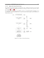
Страница 137: ...C 5 Option 04 Parallel BCD Output 117 C 5 2 Option 04 Firmware Setup Figure C 2 Option 04 Firmware Setup ...
Страница 145: ...C 5 Option 04 Parallel BCD Output 125 Figure C 4 Option 04 Output Jumper Settings ...
Страница 146: ...126 Options List Figure C 5 Option 04 Board Layout and Jumper Locations ...
Страница 165: ...C 12 Option 17 Parallel BCD Output and Second RS 232 Port 145 Figure C 11 Option 17 Output Jumper Settings ...
Страница 166: ...146 Options List Figure C 12 Option 17 Board Layout and Jumper Locations ...
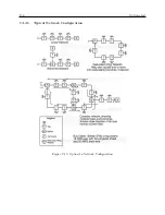
Страница 176: ...156 Options List C 14 5 Typical Network Configuration Figure C 15 Option 18 Network Configuration ...
Страница 187: ...C 16 Option 20A Four Fiber Optic Outputs 167 Figure C 22 Option 20A Jumper Locations ...
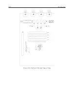
Страница 194: ...174 Options List Figure C 24 Option 23 Internal Jumper Setup ...
Страница 196: ...176 Options List Figure C 25 Option 27 Jumper Locations ...
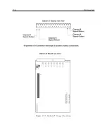
Страница 214: ...194 Options List Figure C 28 Option 29 Connector Signal Locations ...
Страница 270: ...250 Options List ...


