


17.
AMPLITUDE
A
CCURA
CY/FREQUENCY
RESPONSE
TEST
(SA)
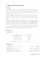
Description
This
test
measures
the
amplitude
measuremen
t
accuracy
of
the
4395A
sp ectrum
measuremen
t
o
v
er
the
en
tire
frequency
range.
The
frequency
resp onse
is
calculated
as
the
accuracy
deviation
from
the
absolute
amplitude
accuracy
at
a
frequency
of
50
MHz.
A
t
frequency
ranges
1
MHz,
this
test
applies
a
CW
signal
to
the
4395A
input
and
p o
w
er
meter
through
a
p o
w
er
splitter.
The
signal
lev
el
is
measured
b
y
doing
a
4395A
sp ectrum
measuremen
t
using
a
p o
w
er
meter
and
a
p o
w
er
sensor.
Then
the
4395A
reading
is
compared
with
the
reading
of
the
p o
w
er
meter
to
obtain
the
absolute
amplitude
accuracy
.
These
tests
are
p erformed
t
wice
while
rev
ersing
connections
of
the
p o
w
er
splitter's
t
w
o
output
p orts.
This
is
done
to
remov
e
the
frequency
tracking
b et
w
een
t
w
o
output
p orts
of
the
p o
w
er
splitter.
A
t
low
frequencies
( <
1
MHz),
this
test
measures
the
CW
signal
lev
el
of
the
function
generator
using
the
4395A
sp ectrum
measuremen
t.
The
function
generator's
output
lev
el
is
used
as
the
measuremen
t
standard.
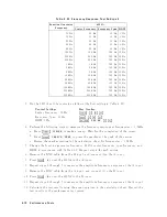
Specification
Amplitude
accuracy
@020
dBm
input,
50
MHz,
input
att.=
10
dB,
23 65
C
:
:
:
:
:
:
:
:
:
:
:
:
:
:
:
:
:
:
:
:
:
:
:
<60.8
dB
F
requency
resp onse
@020
dBm
input,
input
att.=
10dB,
referenced
to
lev
el
at
50
MHz,
23 65
C
frequency
100
Hz
:
:
:
:
:
:
:
:
:
:
:
:
:
:
:
:
:
:
:
:
:
:
:
:
:
:
:
:
:
:
:
:
:
:
:
:
:
:
:
:
:
:
:
:
:
:
:
:
:
:
:
:
:
:
:
:
<61.3
dB
frequency
<
100
Hz
:
:
:
:
:
:
:
:
:
:
:
:
:
:
:
:
:
:
:
:
:
:
:
:
:
:
:
:
:
:
:
:
:
:
:
:
:
:
:
:
:
:
:
:
:
:
:
:
:
:
:
:
:
:
:
:
<63.0
dB
T
est
Equipment
P
o
w
er
Meter
:
:
:
:
:
:
:
:
:
:
:
:
:
:
:
:
:
:
:
:
:
:
:
:
:
:
:
:
:
:
:
:
:
:
:
:
:
:
:
:
:
:
:
:
:
:
:
436A
Opt.
022,
437B,
or
438A
P
o
w
er
Sensor
:
:
:
:
:
:
:
:
:
:
:
:
:
:
:
:
:
:
:
:
:
:
:
:
:
:
:
:
:
:
:
:
:
:
:
:
:
:
:
:
:
:
:
:
:
:
:
:
:
:
:
:
:
:
:
:
:
:
:
:
:
:
:
:
:
:
:
:
:
:
:
8482A
Signal
Generator
:
:
:
:
:
:
:
:
:
:
:
:
:
:
:
:
:
:
:
:
:
:
:
:
:
:
:
:
:
:
:
:
:
:
:
:
:
:
:
:
:
:
:
:
:
:
:
:
:
:
:
:
:
:
:
:
:
:
:
:
:
:
:
:
:
:
:
8663A
F
unction
Genarator
:
:
:
:
:
:
:
:
:
:
:
:
:
:
:
:
:
:
:
:
:
:
:
:
:
:
:
:
:
:
:
:
:
:
:
:
:
:
:
:
:
:
:
:
:
:
:
:
:
:
:
:
:
:
:
:
:
:
:
:
:
:
:
:
:
3325A
Tw
o-W
a
y
P
o
w
er
Splitter
:
:
:
:
:
:
:
:
:
:
:
:
:
:
:
:
:
:
:
:
:
:
:
:
:
:
:
:
:
:
:
:
:
:
:
:
:
:
:
:
:
:
:
:
:
:
:
:
:
:
:
:
:
:
:
:
:
:
:
11667A
T
yp e-N
Cable,
61
cm
:
:
:
:
:
:
:
:
:
:
:
:
:
:
:
:
:
:
:
:
:
:
:
:
:
:
:
:
:
:
:
:
:
:
:
:
:
:
:
:
:
:
:
:
11500B
or
part
of
11851B
BNC
cable,
61
cm
:
:
:
:
:
:
:
:
:
:
:
:
:
:
:
:
:
:
:
:
:
:
:
:
:
:
:
:
:
:
:
:
:
:
:
:
:
:
:
:
:
:
:
:
:
:
:
:
:
:
:
:
:
:
:
:
:
:
:
PN
8120-1839
BNC
cable,
122
cm
:
:
:
:
:
:
:
:
:
:
:
:
:
:
:
:
:
:
:
:
:
:
:
:
:
:
:
:
:
:
:
:
:
:
:
:
:
:
:
:
:
:
:
:
:
:
:
:
:
:
:
:
:
:
:
:
:
PN
8120-1840
N(m)-N(m)
adapter
:
:
:
:
:
:
:
:
:
:
:
:
:
:
:
:
:
:
:
:
:
:
:
:
:
:
:
:
:
:
:
:
:
:
:
:
:
:
:
:
:
:
:
:
:
:
:
:
:
:
:
:
:
:
:
:
:
PN
1250-1475
N(m)-BNC(f
)
adapter
:
:
:
:
:
:
:
:
:
:
:
:
:
:
:
:
:
:
:
:
:
:
:
:
:
:
:
:
:
:
:
:
:
:
:
:
:
:
:
:
:
:
:
:
:
:
:
:
:
:
:
:
:
:
:
PN
1250-0780
Procedure
1.
F
or
testing
high
frequencies
a.
Connect
the
p o
w
er
sensor
to
the
p o
w
er
meter.
Calibrate
the
p o
w
er
meter
for
the
p o
w
er
sensor.
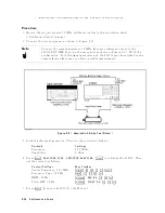
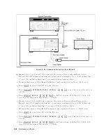
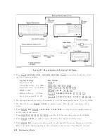
b.
Connect
the
test
equipmen
t
as
sho
wn
in
Figure
2-24.
P
erformance
T
ests
2-65
Содержание 4395A
Страница 10: ......
Страница 26: ......
Страница 34: ......
Страница 77: ...Figure 2 17 B R Magnitude Ratio Phase Dynamic Accuracy Test Setup 2 Performance Tests 2 43 ...
Страница 167: ...Figure 5 1 Adjustment Hardware Setup Adjustments 5 5 ...
Страница 186: ...Figure 5 13 Receiver Gain Adjustment Location 5 24 Adjustments ...
Страница 190: ...Figure 5 16 Receiver Flatness Adjustment Setup 1 MHz 5 28 Adjustments ...
Страница 194: ...Figure 5 20 DC Bias Adjustment Setup 2 5 32 Adjustments ...
Страница 196: ...Figure 6 1 Troubleshooting Organization 6 2 Troubleshooting ...
Страница 206: ...Figure 7 1 Power Supply Lines Simplified Block Diagram 7 2 Power Supply Troubleshooting ...
Страница 212: ...Figure 7 5 A1 CPU Connector Locations 7 8 Power Supply Troubleshooting ...
Страница 220: ...Figure 8 1 Digital Control Group Simplified Block Diagram 8 2 Digital Control Troubleshooting ...
Страница 240: ...Figure 10 1 Top View Major Assemblies 10 4 Replaceable Parts ...
Страница 292: ...Table A 2 Manual Changes by Firmware Version Version Make Manual Changes A 2 Manual Changes ...
Страница 303: ...Change 6 Change the Replaceable Parts as following Figure A 10 Top View Major Assemblies Manual Changes A 13 ...
Страница 308: ......
Страница 311: ...Figure B 1 Power Cable Supplied Power Requirement B 3 ...
Страница 312: ......
Страница 342: ......


