


ST
ART
HERE
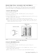
1.
Check
the
P
o
w
er-On
Sequence
See
the
INSPECT
THE
PO
WER-ON
SEQUENCE
in
the
c
hapter
6
for
c
hec
king
the
P
o
w
er-On
Sequence.
Check
the
4
Ch
1
5
and
4
Ch
2
5
Operations
a.
Press
4
Ch
1
5
and
4
Ch
2
5
alternately
.
b.
Chec
k
that
the
t
w
o
LEDs
alternately
light
eac
h
time
y
ou
press
the
k
eys.
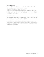
If
b oth
LEDs
w
ould
not
light,
con
tinue
with
the
next
Che
ck
the
A1
Eight
LEDs.
If
the
t
w
o
LEDs
do
not
alternately
light
(the
4
Ch
1
5
LED
is
still
lit
ev
en
if
pressing
the
4
Ch
2
5),
the
A1
CPU
is
probably
faulty
.
Replace
the
A1
CPU.
If
the
t
w
o
LEDs
alternately
light
eac
h
time
y
ou
press
the
k
eys,
the
A1
CPU
is
probably
w
orking
prop erly
.
Con
tinue
with
the
TR
OUBLESHOOT
THE
A51
GSP
AND
A52
LCD
in
this
c
hapter.
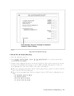
Check
the
A1
Eight
LEDs
There
are
eigh
t
LEDs
on
the
A1
CPU.
These
LEDs
should
b e
in
the
pattern
sho
wn
in
Figure
8-5
at
the
end
of
the
p o
w
er
on
sequence.
P
erform
the
follo
wing
pro cedure
to
c
hec
k
the
A1
eigh
t
LEDs.
a.
T
urn
the
analyzer
turn
o.
b.
Remo
v
e
the
b ottom
co
v
er
of
the
analyzer.
c.
T
urn
the
analyzer
p o
w
er
on.
d.
Lo ok
at
the
A1
eigh
t
LEDs.
Some
of
the
LEDs
light
during
the
p o
w
er
on
sequence.
A
t
the
end
of
the
p o
w
er
on
sequence,
the
LEDs
should
stay
in
the
pattern
sho
wn
in
Figure
8-5.
If
the
LEDs
stay
in
the
other
pattern,
the
A1
CPU
is
probably
faulty
.
Replace
the
A1
CPU.
8-6
Digital
Control
Troubleshooting
Содержание 4395A
Страница 10: ......
Страница 26: ......
Страница 34: ......
Страница 77: ...Figure 2 17 B R Magnitude Ratio Phase Dynamic Accuracy Test Setup 2 Performance Tests 2 43 ...
Страница 167: ...Figure 5 1 Adjustment Hardware Setup Adjustments 5 5 ...
Страница 186: ...Figure 5 13 Receiver Gain Adjustment Location 5 24 Adjustments ...
Страница 190: ...Figure 5 16 Receiver Flatness Adjustment Setup 1 MHz 5 28 Adjustments ...
Страница 194: ...Figure 5 20 DC Bias Adjustment Setup 2 5 32 Adjustments ...
Страница 196: ...Figure 6 1 Troubleshooting Organization 6 2 Troubleshooting ...
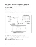
Страница 206: ...Figure 7 1 Power Supply Lines Simplified Block Diagram 7 2 Power Supply Troubleshooting ...
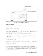
Страница 212: ...Figure 7 5 A1 CPU Connector Locations 7 8 Power Supply Troubleshooting ...
Страница 220: ...Figure 8 1 Digital Control Group Simplified Block Diagram 8 2 Digital Control Troubleshooting ...
Страница 240: ...Figure 10 1 Top View Major Assemblies 10 4 Replaceable Parts ...
Страница 292: ...Table A 2 Manual Changes by Firmware Version Version Make Manual Changes A 2 Manual Changes ...
Страница 303: ...Change 6 Change the Replaceable Parts as following Figure A 10 Top View Major Assemblies Manual Changes A 13 ...
Страница 308: ......
Страница 311: ...Figure B 1 Power Cable Supplied Power Requirement B 3 ...
Страница 312: ......
Страница 342: ......


