


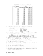


Figure
2-28.
Third
Order
Intermodulation
Distortion
T
est
Setup
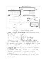
2.
Initialize
b oth
signal
generators.
Then
set
their
con
trols
as
follo
ws:
Con
trols
Settings
Mo
dulation
OFF
Amplitude
010
dBm
RF
Signal
OFF
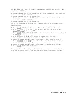
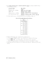
3.
Press
4
Meas
5,
NNNNNNNNNNNNNNNNNNNNNNNNNNNNNNNNNNNNNNNNN
ANALYZER
TYPE
,
NNNNNNNNNNNNNNNNNNNNNNNNNNNNNNNNNNNNNNNNNNNNNNNNNNNNN
SPECTRUM
ANALYZER
,
4
Preset
5
to
initialize
the
4395A.
Then
set
the
con
trols
as
follo
ws:
Con
trol
Settings
Key
Strok
es
Input
P
ort:
R
4
Meas
5
NNNNN
R
Cen
ter
F
requency:
100.25
MHz
4
Center
5
4
1
5,
4
0
5,
4
0
5,
4
.
5,
4
2
5,
4
5
5,
4
M/
5
F
requency
Span:
400
kHz
4
Span
5,
4
4
5,
4
0
5,
4
0
5,
4
k/m
5
RBW:
1
kHz
4
Bw/Avg
5,
NNNNNNNNNNNNNNNNNNNN
RES
BW
,
4
1
5,
4
k/m
5
Video
BW:
1
kHz
4
Bw/Avg
5,
NNNNNNNNNNNNNNNNNNNNNNNNNN
VIDEO
BW
,
4
1
5,
4
k/m
5
Reference
Lev
el:
010
dBm
4
Scale
Ref
5,
NNNNNNNNNNNNNNNNNNNNNNNNNNNNNNNNNNNNNNNNNNNNNNN
REFERENCE
VALUE
,
4
-
5,
4
1
5,
4
0
5,
4
x1
5
Input
A
tten
uator
R:
10
dB
4
Scale
Ref
5,
NNNNNNNNNNNNNNNNNNNNNNNNNNNNNNNNNNNNNNNNNNNNNNN
ATTENUATOR
MENU
,
NNNNNNNNNNNNNNNNNNNNNNN
ATTEN
R
,
4
1
5,
4
0
5,
4
x1
5
4.
On
signal
generator
1,
set
the
frequency
to
100.2
MHz.
5.
On
signal
generator
2,
set
the
frequency
to
100.3
MHz.
2-74
P
erformance
T
ests
Содержание 4395A
Страница 10: ......
Страница 26: ......
Страница 34: ......
Страница 77: ...Figure 2 17 B R Magnitude Ratio Phase Dynamic Accuracy Test Setup 2 Performance Tests 2 43 ...
Страница 167: ...Figure 5 1 Adjustment Hardware Setup Adjustments 5 5 ...
Страница 186: ...Figure 5 13 Receiver Gain Adjustment Location 5 24 Adjustments ...
Страница 190: ...Figure 5 16 Receiver Flatness Adjustment Setup 1 MHz 5 28 Adjustments ...
Страница 194: ...Figure 5 20 DC Bias Adjustment Setup 2 5 32 Adjustments ...
Страница 196: ...Figure 6 1 Troubleshooting Organization 6 2 Troubleshooting ...
Страница 206: ...Figure 7 1 Power Supply Lines Simplified Block Diagram 7 2 Power Supply Troubleshooting ...
Страница 212: ...Figure 7 5 A1 CPU Connector Locations 7 8 Power Supply Troubleshooting ...
Страница 220: ...Figure 8 1 Digital Control Group Simplified Block Diagram 8 2 Digital Control Troubleshooting ...
Страница 240: ...Figure 10 1 Top View Major Assemblies 10 4 Replaceable Parts ...
Страница 292: ...Table A 2 Manual Changes by Firmware Version Version Make Manual Changes A 2 Manual Changes ...
Страница 303: ...Change 6 Change the Replaceable Parts as following Figure A 10 Top View Major Assemblies Manual Changes A 13 ...
Страница 308: ......
Страница 311: ...Figure B 1 Power Cable Supplied Power Requirement B 3 ...
Страница 312: ......
Страница 342: ......


