


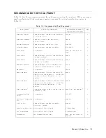


T
able
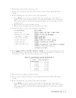
1-3.
Calibration
Data
Required
for
8496G
Opt.
001
and
H60
F
requency
A
tten
uation
Uncertain
t
y
50
MHz
0
dB
0.0037
dB
10
dB
0.0042
dB
20
dB
0.0046
dB
30
dB
0.0052
dB
40
dB
0.0079
dB
50
dB
0.0125
dB
60
dB
0.0144
dB
70
dB
0.0327
dB
80
dB
0.0532
dB
90
dB
0.0543
dB
100
dB
0.0850
dB
The
calibration
uncertain
t
y
is
the
primary
source
of
measuremen
t
error
in
p erformance
tests.
The
measuremen
t
uncertain
ties
listed
in
the
p erformance
test
record
of
Chapter
4
are
v
alid
only
when
the
uncertain
t
y
of
the
step
attenuation
data
satises
that
given
in
the
third
column
of
T
able
1-3.
The
calibration
of
step
attenuators,
8496G
Opt.
001
and
H60,
are
a
v
ailable
at
Agilent
T
ec
hnologies.
F
or
information
ab out
the
calibration
and
the
a
v
ailable
uncertain
ties,
con
tact
y
our
nearest
Agilent
T
ec
hnologies
service
cen
ter.
Note
The
8496G
Opt.
001
and
H60
programmable
step
attenuator
has
four
attenuation
segmen
ts,
10
dB
segmen
t,
20
dB
segmen
t,
and
t
w
o
40
dB
segmen
ts.
Eac
h
attenuation
from
10
dB
to
70
dB
is
obtained
b
y
com
bining
these
segmen
ts.
The
attenuations
from
40
dB
to
70
dB
dep end
on
the
40
dB
segmen
t
that
is
used.
When
setting
the
step
attenuator
for
the
calibration,
sp ecify
one
of
the
40
dB
segmen
ts
for
attenuations
from
40
dB
to
70
dB.
Then
use
the
sp ecied
segmen
t
in
the
tests.
General
Information
1-7
Содержание 4395A
Страница 10: ......
Страница 26: ......
Страница 34: ......
Страница 77: ...Figure 2 17 B R Magnitude Ratio Phase Dynamic Accuracy Test Setup 2 Performance Tests 2 43 ...
Страница 167: ...Figure 5 1 Adjustment Hardware Setup Adjustments 5 5 ...
Страница 186: ...Figure 5 13 Receiver Gain Adjustment Location 5 24 Adjustments ...
Страница 190: ...Figure 5 16 Receiver Flatness Adjustment Setup 1 MHz 5 28 Adjustments ...
Страница 194: ...Figure 5 20 DC Bias Adjustment Setup 2 5 32 Adjustments ...
Страница 196: ...Figure 6 1 Troubleshooting Organization 6 2 Troubleshooting ...
Страница 206: ...Figure 7 1 Power Supply Lines Simplified Block Diagram 7 2 Power Supply Troubleshooting ...
Страница 212: ...Figure 7 5 A1 CPU Connector Locations 7 8 Power Supply Troubleshooting ...
Страница 220: ...Figure 8 1 Digital Control Group Simplified Block Diagram 8 2 Digital Control Troubleshooting ...
Страница 240: ...Figure 10 1 Top View Major Assemblies 10 4 Replaceable Parts ...
Страница 292: ...Table A 2 Manual Changes by Firmware Version Version Make Manual Changes A 2 Manual Changes ...
Страница 303: ...Change 6 Change the Replaceable Parts as following Figure A 10 Top View Major Assemblies Manual Changes A 13 ...
Страница 308: ......
Страница 311: ...Figure B 1 Power Cable Supplied Power Requirement B 3 ...
Страница 312: ......
Страница 342: ......


