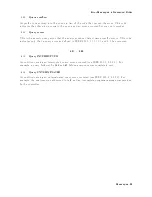
Error
Messages
in
Numerical
Order
0280
Program
error
Indicates
that
a
do
wnloaded
program-related
execution
error
o ccurred.
This
error
message
is
used
when
the
analyzer
cannot
detect
the
more
sp ecic
errors
describ ed
for
errors
0281
through
0289.
0281
Cannot
create
program
Indicates
that
an
attempt
to
create
a
program
w
as
unsuccessful.
A
reason
for
the
failure
might
include
not
enough
memory
.
0282
Illegal
program
name
The
name
used
to
reference
a
program
w
as
in
v
alid.
F
or
example,
redening
an
existing
program,
deleting
a
nonexisten
t
program,
or
in
general,
referencing
a
nonexisten
t
program.
0283
Illegal
v
ariable
name
An
attempt
w
as
made
to
reference
a
nonexisten
t
v
ariable
in
a
program.
0284
Program
curren
tly
running
Certain
op erations
dealing
with
programs
may
b e
illegal
while
the
program
is
running.
F
or
example,
deleting
a
running
program
might
not
b e
p ossible.
0285
Program
syn
tax
error
Indicates
that
a
syn
tax
error
app ears
in
a
do
wnloaded
program.
The
syn
tax
used
when
parsing
the
do
wnloaded
program
is
device-sp ecic.
0286
Program
run
time
error
A
program
run
time
error
of
the
HP
Instrumen
t
BASIC
has
o ccurred.
T
o
get
a
more
sp ecic
error
information,
use
the
ERRM$
or
ERRN
command
of
the
HP
Instrumen
t
BASIC.
0301
-
0400
0310
System
error
Some
error,
termed
\system
error"
b
y
the
analyzer,
has
o ccurred.
0311
Memory
error
An
error
w
as
detected
in
the
analyzer's
memory
.
0330
Self-test
failed
A
self-test
failed.
Con
tact
y
our
nearest
Agilent
T
ec
hnologies
oce
or
see
the
Servic
e
Manual
for
troublesho
oting.
Messages-28
Содержание 4395A
Страница 10: ......
Страница 26: ......
Страница 34: ......
Страница 77: ...Figure 2 17 B R Magnitude Ratio Phase Dynamic Accuracy Test Setup 2 Performance Tests 2 43 ...
Страница 167: ...Figure 5 1 Adjustment Hardware Setup Adjustments 5 5 ...
Страница 186: ...Figure 5 13 Receiver Gain Adjustment Location 5 24 Adjustments ...
Страница 190: ...Figure 5 16 Receiver Flatness Adjustment Setup 1 MHz 5 28 Adjustments ...
Страница 194: ...Figure 5 20 DC Bias Adjustment Setup 2 5 32 Adjustments ...
Страница 196: ...Figure 6 1 Troubleshooting Organization 6 2 Troubleshooting ...
Страница 206: ...Figure 7 1 Power Supply Lines Simplified Block Diagram 7 2 Power Supply Troubleshooting ...
Страница 212: ...Figure 7 5 A1 CPU Connector Locations 7 8 Power Supply Troubleshooting ...
Страница 220: ...Figure 8 1 Digital Control Group Simplified Block Diagram 8 2 Digital Control Troubleshooting ...
Страница 240: ...Figure 10 1 Top View Major Assemblies 10 4 Replaceable Parts ...
Страница 292: ...Table A 2 Manual Changes by Firmware Version Version Make Manual Changes A 2 Manual Changes ...
Страница 303: ...Change 6 Change the Replaceable Parts as following Figure A 10 Top View Major Assemblies Manual Changes A 13 ...
Страница 308: ......
Страница 311: ...Figure B 1 Power Cable Supplied Power Requirement B 3 ...
Страница 312: ......
Страница 342: ......


