


P
o
w
er
Requirements
The
4395A
requires
the
follo
wing
p o
w
er
source:
V
oltage
:
90
to
132
V
ac,
198
to
264
V
ac
F
requency
:
47
to
63
Hz
P
o
w
er
:
300
V
A
maximum
P
o
w
er
Cable
In
accordance
with
in
ternational
safety
standards,
this
instrumen
t
is
equipp ed
with
a
three-wire
p o
w
er
cable.
When
connected
to
an
appropriate
ac
p o
w
er
outlet,
this
cable
grounds
the
instrumen
t
frame.
The
t
yp e
of
p o
w
er
cable
shipp ed
with
eac
h
instrumen
t
dep ends
on
the
coun
try
of
destination.
Refer
to
Figure
B-1
for
the
part
n
um
b ers
of
the
p o
w
er
cables
a
v
ailable.
W
arning
For
protection
from
electrical
shock,
the
po
w
er
cable
ground
must
not
be
defeated.
The
po
w
er
plug
must
be
plugged
into
an
outlet
that
pro
vides
a
protectiv
e
earth
ground
connection.
B-2
P
o
w
er
Requirement
Содержание 4395A
Страница 10: ......
Страница 26: ......
Страница 34: ......
Страница 77: ...Figure 2 17 B R Magnitude Ratio Phase Dynamic Accuracy Test Setup 2 Performance Tests 2 43 ...
Страница 167: ...Figure 5 1 Adjustment Hardware Setup Adjustments 5 5 ...
Страница 186: ...Figure 5 13 Receiver Gain Adjustment Location 5 24 Adjustments ...
Страница 190: ...Figure 5 16 Receiver Flatness Adjustment Setup 1 MHz 5 28 Adjustments ...
Страница 194: ...Figure 5 20 DC Bias Adjustment Setup 2 5 32 Adjustments ...
Страница 196: ...Figure 6 1 Troubleshooting Organization 6 2 Troubleshooting ...
Страница 206: ...Figure 7 1 Power Supply Lines Simplified Block Diagram 7 2 Power Supply Troubleshooting ...
Страница 212: ...Figure 7 5 A1 CPU Connector Locations 7 8 Power Supply Troubleshooting ...
Страница 220: ...Figure 8 1 Digital Control Group Simplified Block Diagram 8 2 Digital Control Troubleshooting ...
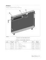
Страница 240: ...Figure 10 1 Top View Major Assemblies 10 4 Replaceable Parts ...
Страница 292: ...Table A 2 Manual Changes by Firmware Version Version Make Manual Changes A 2 Manual Changes ...
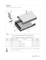
Страница 303: ...Change 6 Change the Replaceable Parts as following Figure A 10 Top View Major Assemblies Manual Changes A 13 ...
Страница 308: ......
Страница 311: ...Figure B 1 Power Cable Supplied Power Requirement B 3 ...
Страница 312: ......
Страница 342: ......


