


FIND
OUT
WHY
THE
F
AN
IS
NOT
ROT
A
TING
If
the
fan
is
not
rotating,
the
problem
may
b e
in
the
A40
pre-regulator,
the
A50
DC-DC
Con
v
erter
or
the
fan.
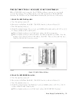
1.
Check
the
Line
V
oltage,
Selector
Switch
Setting,
and
Fuse
Chec
k
the
main
p o
w
er
line
cord,
line
fuse,
and
actual
line
v
oltage
to
see
that
they
are
all
correct.
Figure
7-4
sho
ws
ho
w
to
remov
e
the
line
fuse,
using
a
small
at-bladed
screwdriver
to
pry
o
the
fuse
holder.
F
or
more
information
ab out
the
line
cord
and
line
fuse,
see
the
Power
R
e
quir
ements
in
App endix
C.
Figure
7-4.
Remo
ving
Line
Fuse
2.
Check
the
A50
SHUTDO
WN
LED
When
the
fan
stops,
the
A50
SHUTDO
WN
LED
is
o.
The
fan
generates
a
F
AN
LOCK
signal.
The
signal
is
fed
in
to
the
F
AN
LOCK
SENSE
circuit
in
the
A50
DC-DC
con
v
erter.
If
the
F
AN
stops,
the
F
AN
LOCK
signal
is
missing.
Then
the
F
AN
LOCK
SENSE
circuit
activ
ates
the
A50
sh
utdo
wn
circuitry
,
resulting
the
SHUTDO
WN
LED
turned
o.
P
erform
the
following
pro cedure
to
c
hec
k
the
A50
SHUTDO
WN
LED
on.
a.
Remo
v
e
the
analyzer's
top
co
v
er
and
shield
plate.
b.
T
urn
the
analyzer
p o
w
er
on.
c.
Lo ok
at
the
A50
SHUTDO
WN
LED.
The
LED
lo
cation
is
sho
wn
in
Figure
7-2 .
If
the
SHUTDO
WN
LED
is
on,
replace
the
A50
DC-DC
Con
v
erter.
If
the
SHUTDO
WN
LED
is
o,
con
tinue
with
the
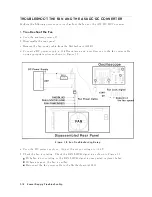
TR
OUBLESHOOT
THE
F
AN
AND
THE
A50
DC-DC
Converter
in
this
c
hapter.
7-6
P
o
w
er
Supply
Troubleshooting
Содержание 4395A
Страница 10: ......
Страница 26: ......
Страница 34: ......
Страница 77: ...Figure 2 17 B R Magnitude Ratio Phase Dynamic Accuracy Test Setup 2 Performance Tests 2 43 ...
Страница 167: ...Figure 5 1 Adjustment Hardware Setup Adjustments 5 5 ...
Страница 186: ...Figure 5 13 Receiver Gain Adjustment Location 5 24 Adjustments ...
Страница 190: ...Figure 5 16 Receiver Flatness Adjustment Setup 1 MHz 5 28 Adjustments ...
Страница 194: ...Figure 5 20 DC Bias Adjustment Setup 2 5 32 Adjustments ...
Страница 196: ...Figure 6 1 Troubleshooting Organization 6 2 Troubleshooting ...
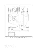
Страница 206: ...Figure 7 1 Power Supply Lines Simplified Block Diagram 7 2 Power Supply Troubleshooting ...
Страница 212: ...Figure 7 5 A1 CPU Connector Locations 7 8 Power Supply Troubleshooting ...
Страница 220: ...Figure 8 1 Digital Control Group Simplified Block Diagram 8 2 Digital Control Troubleshooting ...
Страница 240: ...Figure 10 1 Top View Major Assemblies 10 4 Replaceable Parts ...
Страница 292: ...Table A 2 Manual Changes by Firmware Version Version Make Manual Changes A 2 Manual Changes ...
Страница 303: ...Change 6 Change the Replaceable Parts as following Figure A 10 Top View Major Assemblies Manual Changes A 13 ...
Страница 308: ......
Страница 311: ...Figure B 1 Power Cable Supplied Power Requirement B 3 ...
Страница 312: ......
Страница 342: ......


