


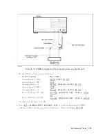


9.
INPUT
IMPED
ANCE
TEST
(NA)
Description
This
test
uses
a
net
w
ork
analyzer
and
a
T/R
test
set
to
measure
the
return
losses
of
the
4395A
R,
A,
and
B
inputs.
One-p
ort
full
calibration
is
p erformed
to
measured
the
return
loss
accurately
.
The
4395A
has
no
capabilit
y
for
making
an
A/B
measuremen
t.
The
4395A
can
measure
the
return
loss
of
the
B
(or
A)
input
using
A/R
(or
B/R)
measuremen
t
capabilit y
of
the
4395A.
Ho
w
ev
er,
it
cannot
measure
the
R
input's
return
loss.
Therefore,
a
net
w
ork
analyzer
is
used
in
this
test.
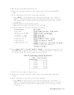
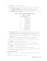
Specification
Return
Loss
(@att.=10
dB)
Return
Loss
F
requency
@att.=10
dB
100
kHz
freq.
100
MHz
25
dB
100
MHz
<
freq.
15
dB
T
est
Equipment
Net
w
ork
Analyzer
:
:
:
:
:
:
:
:
:
:
:
:
:
:
:
:
:
:
:
:
:
:
:
:
:
:
:
:
:
:
:
:
:
:
:
:
:
:
:
:
:
:
:
:
:
:
:
:
:
:
:
:
:
:
:
:
:
:
:
:
:
8753A/B/C
T/R
T
est
Sets
:
:
:
:
:
:
:
:
:
:
:
:
:
:
:
:
:
:
:
:
:
:
:
:
:
:
:
:
:
:
:
:
:
:
:
:
:
:
:
:
:
:
:
:
:
:
:
:
:
:
:
:
:
:
:
:
:
:
:
:
:
:
:
:
:
:
:
:
:
85044A
50
T
yp e-N
Calibration
Kit
:
:
:
:
:
:
:
:
:
:
:
:
:
:
:
:
:
:
:
:
:
:
:
:
:
:
:
:
:
:
:
:
:
:
:
:
:
:
:
:
:
:
:
:
:
:
:
:
:
:
:
:
:
:
85032B
1
APC7.5-N(f
)
adapter
:
:
:
:
:
:
:
:
:
:
:
:
:
:
:
:
:
:
:
:
:
:
:
:
:
:
:
:
:
:
:
:
:
:
:
:
:
:
:
:
:
:
:
:
11524A
or
part
of
85032B
T
yp e-N
Cable,
61
cm
(four
required)
:
:
:
:
:
:
:
:
:
:
:
:
:
:
:
:
:
:
:
:
:
:
:
:
:
:
:
:
11500B
or
part
of
11851B
1:
This
calibration
kit
includes
several
terminations
and
adapters.
This
test
requires
the
OPEN(f
),
SHOR
T(f
),
LO
AD(f
)
in
the
calibration
kit
85032B .
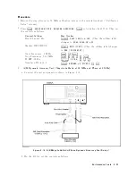
Procedure
1.
Connect
the
test
equipmen
t
as
sho
wn
in
Figure
2-11 .
Don't
connect
an
ything
to
the
end
of
the
test
p ort
cable.
P
erformance
T
ests
2-27
Содержание 4395A
Страница 10: ......
Страница 26: ......
Страница 34: ......
Страница 77: ...Figure 2 17 B R Magnitude Ratio Phase Dynamic Accuracy Test Setup 2 Performance Tests 2 43 ...
Страница 167: ...Figure 5 1 Adjustment Hardware Setup Adjustments 5 5 ...
Страница 186: ...Figure 5 13 Receiver Gain Adjustment Location 5 24 Adjustments ...
Страница 190: ...Figure 5 16 Receiver Flatness Adjustment Setup 1 MHz 5 28 Adjustments ...
Страница 194: ...Figure 5 20 DC Bias Adjustment Setup 2 5 32 Adjustments ...
Страница 196: ...Figure 6 1 Troubleshooting Organization 6 2 Troubleshooting ...
Страница 206: ...Figure 7 1 Power Supply Lines Simplified Block Diagram 7 2 Power Supply Troubleshooting ...
Страница 212: ...Figure 7 5 A1 CPU Connector Locations 7 8 Power Supply Troubleshooting ...
Страница 220: ...Figure 8 1 Digital Control Group Simplified Block Diagram 8 2 Digital Control Troubleshooting ...
Страница 240: ...Figure 10 1 Top View Major Assemblies 10 4 Replaceable Parts ...
Страница 292: ...Table A 2 Manual Changes by Firmware Version Version Make Manual Changes A 2 Manual Changes ...
Страница 303: ...Change 6 Change the Replaceable Parts as following Figure A 10 Top View Major Assemblies Manual Changes A 13 ...
Страница 308: ......
Страница 311: ...Figure B 1 Power Cable Supplied Power Requirement B 3 ...
Страница 312: ......
Страница 342: ......


