


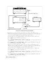


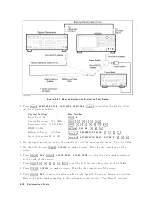


6.
On
signal
generators
1
and
2,
p erform
the
follo
wing
steps
to
adjust
eac
h
generator's
signal
amplitude
to
020
dBm.
a.
On
signal
generator
1,
turn
the
RF
signal
on
and
adjust
the
amplitude
un
til
the
p o
w
er
meter
reads
026
dBm
6
0.1
dB.
b.
On
signal
generator
1,
turn
the
RF
signal
o.
c.
On
signal
generator
2,
turn
the
RF
signal
on
and
adjust
the
amplitude
un
til
the
p o
w
er
meter
reads
026
dBm
6
0.1
dB.
d.
On
signal
generator
1,
turn
the
RF
signal
on.
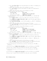
7.
On
the
4395A,
p erform
the
follo
wing
steps
to
measure
the
third
order
in
termo
dulation
distortion
pro duct.
a.
Press
4
T
rigger
5,
NNNNNNNNNNNNNNNNNNNN
SINGLE
to
make
a
sw
eep.
W
ait
for
the
completion
of
the
sw
eep.
b.
Press
4
Ma
rk
er
5,
4
1
5,
4
0
5,
4
0
5,
4
.
5,
4
2
5,
4
M/
5
to
mov
e
the
marker
to
p eak
of
the
signal
generator
1's
signal.
c.
Press
4
Ma
rk
er
5,
NNNNNNNNNNNNNNNNNNNNNNNNNNNNNNNN
1MODE
MENU
,
NNNNNNNNNNNNNNNNNNNNNNNNNNNNNNNN
FIXED
1MKR
to
place
the
delta
marker
reference
at
the
p eak
of
one
carrier.
d.
Press
4
Ma
rk
er
5,
4
-
5,
4
1
5,
4
0
5,
4
0
5,
4
k/m
5
to
mov
e
the
marker
to
the
third
order
in
termo
dulation
distortion
pro ducts
at
the
low
er
frequency
.
e.
Record
the
marker
reading
in
the
calculation
sheet
(\Low
er
F
requency"
column).
f.
Press
4
Ma
rk
er
5,
4
2
5,
4
0
5,
4
0
5,
4
k/m
5
to
mov
e
the
marker
to
the
third
order
in
termo
dulation
distortion
pro duct
at
the
upp
er
frequency
.
g.
Record
the
marker
reading
in
the
calculation
sheet
(\Upp er
F
requency"
column).
h.
Press
4
Ma
rk
er
5,
NNNNNNNNNNNNNNNNNNNNNNNNNNNNNNNN
1MODE
MENU
,
NNNNNNNNNNNNNNNNNNNNNNNNNNNNN
1MODE
OFF
.
8.
Compare
the
t
w
o
marker
readings
at
the
low
er
and
upp er
frequencies
in
the
calculation
sheet.
Record
the
larger
v
alue
in
the
p erformance
test
record
(\T
est
Result"
column).
P
erformance
T
ests
2-75
Содержание 4395A
Страница 10: ......
Страница 26: ......
Страница 34: ......
Страница 77: ...Figure 2 17 B R Magnitude Ratio Phase Dynamic Accuracy Test Setup 2 Performance Tests 2 43 ...
Страница 167: ...Figure 5 1 Adjustment Hardware Setup Adjustments 5 5 ...
Страница 186: ...Figure 5 13 Receiver Gain Adjustment Location 5 24 Adjustments ...
Страница 190: ...Figure 5 16 Receiver Flatness Adjustment Setup 1 MHz 5 28 Adjustments ...
Страница 194: ...Figure 5 20 DC Bias Adjustment Setup 2 5 32 Adjustments ...
Страница 196: ...Figure 6 1 Troubleshooting Organization 6 2 Troubleshooting ...
Страница 206: ...Figure 7 1 Power Supply Lines Simplified Block Diagram 7 2 Power Supply Troubleshooting ...
Страница 212: ...Figure 7 5 A1 CPU Connector Locations 7 8 Power Supply Troubleshooting ...
Страница 220: ...Figure 8 1 Digital Control Group Simplified Block Diagram 8 2 Digital Control Troubleshooting ...
Страница 240: ...Figure 10 1 Top View Major Assemblies 10 4 Replaceable Parts ...
Страница 292: ...Table A 2 Manual Changes by Firmware Version Version Make Manual Changes A 2 Manual Changes ...
Страница 303: ...Change 6 Change the Replaceable Parts as following Figure A 10 Top View Major Assemblies Manual Changes A 13 ...
Страница 308: ......
Страница 311: ...Figure B 1 Power Cable Supplied Power Requirement B 3 ...
Страница 312: ......
Страница 342: ......