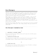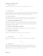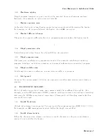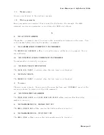
Error
Messages
in
Alphabetical
Order
146
ON
POINT
NOT
ALLO
WD
FOR
THE
CURRENT
TRIG
The
trigger
ev
en
t
mo
de
cannot
b e
c
hanged
to
the
ON
POINT
mo
de
b ecause
the
curren
t
trigger
source
setting
do es
not
allo w
the
ON
POINT
mo
de.
The
ON
POINT
mo
de
is
a
v
ailable
for
only
MANUAL,
EXTERNAL,
and
BUS
trigger
sources
of
the
net
w
ork
analyzer
mo
de.
56
OPTION
NOT
INST
ALLED
This
error
o ccurs
when
an
GPIB
command
whic
h
is
optional
command
is
sen
t
and
the
analyzer
is
not
installed
the
option
( GPIB
only
).
Please
conrm
options
installed
to
the
analyzer
using
*OPT?
command
(see
Pr
o
gr
amming
Manual
.)
45
O
VERLO
AD
ON
INPUT
A
The
p o
w
er
lev
el
at
one
of
the
four
receiv
er
inputs
exceeds
a
certain
lev
el
greater
than
the
maximum
input
lev
el.
44
O
VERLO
AD
ON
INPUT
B
The
p o
w
er
lev
el
at
one
of
the
four
receiv
er
inputs
exceeds
a
certain
lev
el
greater
than
the
maximum
input
lev
el.
46
O
VERLO
AD
ON
INPUT
R
The
p o
w
er
lev
el
at
one
of
the
four
receiv
er
inputs
exceeds
a
certain
lev
el
greater
than
the
maximum
input
lev
el.
P
0220
P
arameter
error
Indicates
that
a
program
data
elemen
t
related
error
o ccurred.
This
error
message
is
used
when
the
analyzer
cannot
detect
the
more
sp ecic
errors
describ ed
for
errors
0221
through
0229.
0108
P
arameter
not
allow
ed
More
parameters
w
ere
receiv
ed
than
exp ected
for
the
header.
F
or
example,
the
*SRE
command
only
accepts
one
parameter,
so
receiving
*SRE
4,16
is
not
allo
w
ed.
48
PHASE
LOCK
LOOP
UNLOCKED
EXT
REF
Input
of
10
MHz
is
not
prop er,
or
the
instrumen
t
is
needed
to
adjust
or
repair.
Chec
k
the
external
reference
signal
rst.
Con
tact
y
our
nearest
Agilent
T
ec
hnologies
oce
for
adjustmen
t
or
repair.
193
PO
WER
ON
TEST
F
AILED
P
o
w
er
on
test
failed.
Con
tact
y
our
nearest
Agilent
T
ec
hnologies
oce.
Messages-11
Содержание 4395A
Страница 10: ......
Страница 26: ......
Страница 34: ......
Страница 77: ...Figure 2 17 B R Magnitude Ratio Phase Dynamic Accuracy Test Setup 2 Performance Tests 2 43 ...
Страница 167: ...Figure 5 1 Adjustment Hardware Setup Adjustments 5 5 ...
Страница 186: ...Figure 5 13 Receiver Gain Adjustment Location 5 24 Adjustments ...
Страница 190: ...Figure 5 16 Receiver Flatness Adjustment Setup 1 MHz 5 28 Adjustments ...
Страница 194: ...Figure 5 20 DC Bias Adjustment Setup 2 5 32 Adjustments ...
Страница 196: ...Figure 6 1 Troubleshooting Organization 6 2 Troubleshooting ...
Страница 206: ...Figure 7 1 Power Supply Lines Simplified Block Diagram 7 2 Power Supply Troubleshooting ...
Страница 212: ...Figure 7 5 A1 CPU Connector Locations 7 8 Power Supply Troubleshooting ...
Страница 220: ...Figure 8 1 Digital Control Group Simplified Block Diagram 8 2 Digital Control Troubleshooting ...
Страница 240: ...Figure 10 1 Top View Major Assemblies 10 4 Replaceable Parts ...
Страница 292: ...Table A 2 Manual Changes by Firmware Version Version Make Manual Changes A 2 Manual Changes ...
Страница 303: ...Change 6 Change the Replaceable Parts as following Figure A 10 Top View Major Assemblies Manual Changes A 13 ...
Страница 308: ......
Страница 311: ...Figure B 1 Power Cable Supplied Power Requirement B 3 ...
Страница 312: ......
Страница 342: ......


