


Error
Messages
in
Numerical
Order
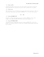
0160
Blo
c
k
data
error
This
error,
as
w
ell
as
errors
0161
and
0168,
are
generated
when
analyzing
the
syn
tax
of
a
blo
c
k
data
elemen
t.
This
particular
error
message
is
used
if
the
analyzer
cannot
detect
a
more
sp ecic
error.
0161
In
v
alid
blo
c
k
data
A
blo
c
k
data
elemen
t
w
as
exp ected,
but
w
as
in
v
alid
for
some
reason
(see
IEEE
488.2,
7.7.6.2).
F
or
example,
an
END
message
w
as
receiv
ed
b efore
the
length
w
as
satised.
0168
Blo
c
k
data
not
allow
ed
A
legal
blo
c
k
data
elemen
t
w
as
encoun
tered
but
w
as
not
allo
w
ed
b
y
the
analyzer
at
this
p oint
in
parsing.
0200
Execution
error
This
is
the
generic
syn
tax
error
that
the
analyzer
cannot
detect
more
sp ecic
errors.
This
co de
indicates
only
that
an
execution
error
as
dened
in
IEEE
488.2,
11.5.1.1.5
has
o ccurred.
0201
-
0300
0210
T
rigger
error
A
trigger
related
error
o ccurred.
This
error
message
is
used
when
the
analyzer
cannot
detect
the
more
sp ecic
errors
describ ed
for
errors
0211
through
0219.
0211
T
rigger
ignored
A
GET,
*TRG ,
or
triggering
signal
w
as
receiv
ed
and
recognized
b
y
the
analyzer
but
w
as
ignored
b ecause
of
analyzer
timing
considerations.
F
or
example,
the
analyzer
w
as
not
ready
to
resp ond.
0213
Init
ignored
A
request
for
a
measuremen
t
initiation
w
as
ignored
as
another
measuremen
t
w
as
already
in
progress.
0220
P
arameter
error
Indicates
that
a
program
data
elemen
t
related
error
o ccurred.
This
error
message
is
used
when
the
analyzer
cannot
detect
the
more
sp ecic
errors
describ ed
for
errors
0221
through
0229.
0221
Settings
conict
A
legal
program
data
elemen
t
w
as
parsed
but
could
not
b e
executed
due
to
the
curren
t
device
state
(see
IEEE
488.2,
6.4.5.3
and
11.5.1.1.5).
Messages-26
Содержание 4395A
Страница 10: ......
Страница 26: ......
Страница 34: ......
Страница 77: ...Figure 2 17 B R Magnitude Ratio Phase Dynamic Accuracy Test Setup 2 Performance Tests 2 43 ...
Страница 167: ...Figure 5 1 Adjustment Hardware Setup Adjustments 5 5 ...
Страница 186: ...Figure 5 13 Receiver Gain Adjustment Location 5 24 Adjustments ...
Страница 190: ...Figure 5 16 Receiver Flatness Adjustment Setup 1 MHz 5 28 Adjustments ...
Страница 194: ...Figure 5 20 DC Bias Adjustment Setup 2 5 32 Adjustments ...
Страница 196: ...Figure 6 1 Troubleshooting Organization 6 2 Troubleshooting ...
Страница 206: ...Figure 7 1 Power Supply Lines Simplified Block Diagram 7 2 Power Supply Troubleshooting ...
Страница 212: ...Figure 7 5 A1 CPU Connector Locations 7 8 Power Supply Troubleshooting ...
Страница 220: ...Figure 8 1 Digital Control Group Simplified Block Diagram 8 2 Digital Control Troubleshooting ...
Страница 240: ...Figure 10 1 Top View Major Assemblies 10 4 Replaceable Parts ...
Страница 292: ...Table A 2 Manual Changes by Firmware Version Version Make Manual Changes A 2 Manual Changes ...
Страница 303: ...Change 6 Change the Replaceable Parts as following Figure A 10 Top View Major Assemblies Manual Changes A 13 ...
Страница 308: ......
Страница 311: ...Figure B 1 Power Cable Supplied Power Requirement B 3 ...
Страница 312: ......
Страница 342: ......


