


PERF
ORMANCE
TESTS
The
analyzer's
p erformance
tests
consist
of
the
21
tests
listed
in
T
able
1-1.
These
tests
v
erify
that
the
analyzer's
p erformance
meets
the
guaranteed
sp ecications.
See
the
Op
er
ation
Manual
for
the
sp ecications.
The
analyzer's
p erformance
is
categorized
in
to
t
w
o
groups;
p erformance
in
the
net
w
ork
analyzer
mo
de
and
p erformance
in
the
sp ectrum
analyzer
mo
de.
The
third
column
in
T
able
1-1
indicates
to
whic
h
group
the
listed
p erformance
test
b elongs.
All
tests
can
b e
p erformed
without
access
to
the
in
terior
of
the
instrumen
t.
The
p erformance
tests
can
b e
used
to
p erform
incoming
insp ection,
and
to
v
erify
that
the
analyzer
meets
p erformance
sp ecications
after
repair.
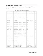
T
able
1-1.
P
erformance
T
ests
T
est
Numb er
T
est
Name
Category
1
1
F
requency
Accuracy
T
est
NA
2
Source
Lev
el
Accuracy/Flatness
T
est
NA
3
Non-sw
eep
Linearit
y
T
est
NA
4
P
o
w
er
Sw
eep
Linearit
y
T
est
NA
5
Harmonics/Non-harmonic
T
est
NA
6
DC
Bias
T
est
(Option
001)
NA
7
Receiv
er
Noise
Lev
el
T
est
NA
8
Input
Crosstalk
T
est
NA
9
Input
Imp
edance
T
est
NA
10
Absolute
Amplitude
Accuracy
T
est
NA
11
Magnitude
Ratio/Phase
Dynamic
Accuracy
T
est
NA
12
Magnitude
Ratio/Phase
F
requency
Resp onse
T
est
NA
13
Displa
y
ed
Av
erage
Noise
Lev
el
T
est
SA
14
Amplitude
Fidelity
T
est
SA
15
Input
A
tten
uator
Switc
hing
Uncertain
t
y
T
est
SA
16
Noise
Sidebands
T
est
SA
17
Amplitude
Accuracy/F
requency
Resp onse
T
est
SA
18
Second
Harmonic
Distortion
T
est
SA
19
Third
Order
In
termo dulation
Distortion
T
est
SA
20
Other
Spurious
T
est
SA
21
Residual
Resp onse
T
est
SA
1
:
NA:
Net
w
ork
Analyzer
Mo de,
SA:
Sp
ectrum
Analyzer
Mo de
The
test
n
um
b ers
in
T
able
1-1
are
n
um
b ered
according
to
the
recommended
sequence
of
p erforming
tests.
When
p erforming
more
than
one
p erformance
test,
p erform
them
in
the
order
listed
in
T
able
1-1 .
The
rst
failed
test
indicates
the
problem
y
ou
should
troublesho
ot
rst.
If
the
p erformance
tests
indicate
that
the
analyzer
is
not
op erating
within
the
sp ecied
limits,
c
hec
k
the
test
setup.
If
the
test
setup
is
correct,
see
the
A
djustments
c
hapter
or
the
T
r
oublesho
oting
c
hapter
for
corrective
action.
Note
Allow
the
analyzer
to
w
arm
up
for
at
least
30
min
utes
b efore
y
ou
execute
an
y
of
the
p erformance
tests.
P
erform
all
p erformance
tests
in
an
ambien
t
temp erature
of
23
6
5
C.
General
Information
1-3
Содержание 4395A
Страница 10: ......
Страница 26: ......
Страница 34: ......
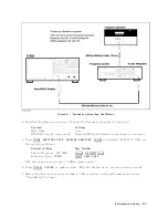
Страница 77: ...Figure 2 17 B R Magnitude Ratio Phase Dynamic Accuracy Test Setup 2 Performance Tests 2 43 ...
Страница 167: ...Figure 5 1 Adjustment Hardware Setup Adjustments 5 5 ...
Страница 186: ...Figure 5 13 Receiver Gain Adjustment Location 5 24 Adjustments ...
Страница 190: ...Figure 5 16 Receiver Flatness Adjustment Setup 1 MHz 5 28 Adjustments ...
Страница 194: ...Figure 5 20 DC Bias Adjustment Setup 2 5 32 Adjustments ...
Страница 196: ...Figure 6 1 Troubleshooting Organization 6 2 Troubleshooting ...
Страница 206: ...Figure 7 1 Power Supply Lines Simplified Block Diagram 7 2 Power Supply Troubleshooting ...
Страница 212: ...Figure 7 5 A1 CPU Connector Locations 7 8 Power Supply Troubleshooting ...
Страница 220: ...Figure 8 1 Digital Control Group Simplified Block Diagram 8 2 Digital Control Troubleshooting ...
Страница 240: ...Figure 10 1 Top View Major Assemblies 10 4 Replaceable Parts ...
Страница 292: ...Table A 2 Manual Changes by Firmware Version Version Make Manual Changes A 2 Manual Changes ...
Страница 303: ...Change 6 Change the Replaceable Parts as following Figure A 10 Top View Major Assemblies Manual Changes A 13 ...
Страница 308: ......
Страница 311: ...Figure B 1 Power Cable Supplied Power Requirement B 3 ...
Страница 312: ......
Страница 342: ......