


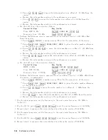


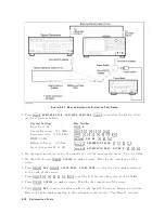


h.
On
the
signal
generator,
set
the
frequency
to
the
rst
frequency
50
MHz
in
the
rst
column
of
T
able
2-22.
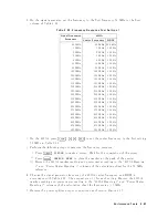
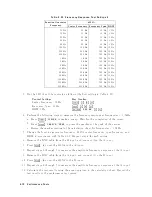
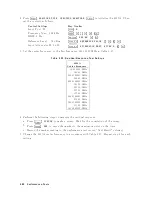
T
able
2-22.
Frequency
Response
T
est
Settings
1
Signal
Generator
F
requency
4395A
Cen
ter
F
requency
RBW
50
MHz
50
MHz
300
kHz
1
MHz
1
MHz
100
Hz
2
MHz
2
MHz
100
Hz
5
MHz
5
MHz
100
Hz
8
MHz
8
MHz
100
Hz
10
MHz
10
MHz
100
Hz
20
MHz
20
MHz
100
Hz
100
MHz
100
MHz
100
Hz
125
MHz
125
MHz
100
Hz
150
MHz
150
MHz
100
Hz
175
MHz
175
MHz
100
Hz
200
MHz
200
MHz
100
Hz
225
MHz
225
MHz
100
Hz
250
MHz
250
MHz
100
Hz
275
MHz
275
MHz
100
Hz
300
MHz
300
MHz
100
Hz
325
MHz
325
MHz
100
Hz
375
MHz
375
MHz
100
Hz
400
MHz
400
MHz
100
Hz
425
MHz
425
MHz
100
Hz
450
MHz
450
MHz
100
Hz
475
MHz
475
MHz
100
Hz
500
MHz
500
MHz
100
Hz
i.
On
the
4395A,
press
4
Center
5,
4
5
5,
4
0
5,
4
M/
5
to
set
the
cen
ter
frequency
to
the
rst
setting
50
MHz
in
T
able
2-22.
j.
P
erform
the
following
steps
to
measure
the
frequency
resp onse.
i.
Press
4
T
rigger
5,
NNNNNNNNNNNNNNNNNNNN
SINGLE
to
make
a
sw
eep.
W
ait
for
the
completion
of
the
sw
eep.
ii.
Press
4
Search
5,
NNNNNNNNNNNNNNNNNNNNNNNNNNNNNNNNNNNNNN
SEARCH:
PEAK
to
place
the
marker
at
the
p eak
of
the
carrier.
iii.
Record
the
4395A
marker
reading
and
p o
w
er
meter
reading
in
the
\ 4395A
Reading
1"
and
\P
o
w
er
Meter
Reading
1"
columns
of
the
calculation
sheet
for
the
50
MHz
reference.
k.
Change
the
signal
generator
frequency
,
the
4395A
cen
ter
frequency
and
RBW
in
accordance
with
T
able
2-22 .
Then
rep eat
step
1-j
for
eac
h
setting.
Record
the
4395A
marker
reading
and
p o
w
er
meter
reading
in
the
\ 4395A
Reading
1"
and
\P
o
w
er
Meter
Reading
1"
columns
of
the
calculation
sheet
for
frequencies
1
MHz.
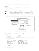
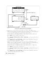
l.
Rev
erse
the
p o
w
er
splitter
output
connections
as
sho
wn
in
Figure
2-25 .
P
erformance
T
ests
2-67
Содержание 4395A
Страница 10: ......
Страница 26: ......
Страница 34: ......
Страница 77: ...Figure 2 17 B R Magnitude Ratio Phase Dynamic Accuracy Test Setup 2 Performance Tests 2 43 ...
Страница 167: ...Figure 5 1 Adjustment Hardware Setup Adjustments 5 5 ...
Страница 186: ...Figure 5 13 Receiver Gain Adjustment Location 5 24 Adjustments ...
Страница 190: ...Figure 5 16 Receiver Flatness Adjustment Setup 1 MHz 5 28 Adjustments ...
Страница 194: ...Figure 5 20 DC Bias Adjustment Setup 2 5 32 Adjustments ...
Страница 196: ...Figure 6 1 Troubleshooting Organization 6 2 Troubleshooting ...
Страница 206: ...Figure 7 1 Power Supply Lines Simplified Block Diagram 7 2 Power Supply Troubleshooting ...
Страница 212: ...Figure 7 5 A1 CPU Connector Locations 7 8 Power Supply Troubleshooting ...
Страница 220: ...Figure 8 1 Digital Control Group Simplified Block Diagram 8 2 Digital Control Troubleshooting ...
Страница 240: ...Figure 10 1 Top View Major Assemblies 10 4 Replaceable Parts ...
Страница 292: ...Table A 2 Manual Changes by Firmware Version Version Make Manual Changes A 2 Manual Changes ...
Страница 303: ...Change 6 Change the Replaceable Parts as following Figure A 10 Top View Major Assemblies Manual Changes A 13 ...
Страница 308: ......
Страница 311: ...Figure B 1 Power Cable Supplied Power Requirement B 3 ...
Страница 312: ......
Страница 342: ......


