


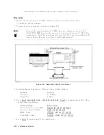


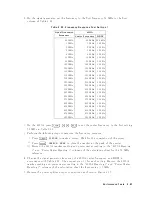


16.
Press
4
Scale
Ref
5,
NNNNNNNNNNNNNNNNNNNNNNNNNNNNNNNNNNNNNNNNNNNNNNN
REFERENCE
VALUE
,
4
-
5,
4
1
5,
4
0
5,
4
x1
5,
4
Scale
Ref
5,
NNNNNNNNNNNNNNNNNNNNNNNNNNNNNNNNNNNNNNNNNNNNNNN
ATTENUATOR
MENU
,
NNNNNNNNNNNNNNNNNNNNNNN
ATTEN
B
,
4
1
5,
4
0
5,
4
x1
5,
to
set
the
4395A
con
trols
to
the
reference
setting
for
the
test.
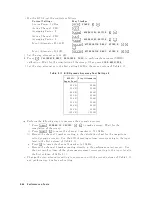
17.
Set
the
step
attenuator
to
10
dB.
18.
Repeat
step
8
to
measure
the
amplitude
delity
at
the
4395A
B
input.
19.
Calculate
the
test
results
using
the
equations
given
in
the
calculation
sheet.
Record
the
test
results
in
the
p erformance
test
record.
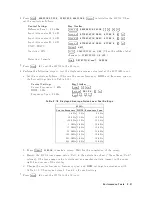
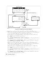
20.
Initialize
the
signal
generator.
Then
set
the
con
trols
as
follo ws:
Con
trols
Settings
F
requency
50.1
MHz
Amplitude
6
dBm
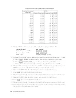
21.
Press
4
Meas
5,
NNNNNNNNNNNNNNNNNNNNNNNNNNNNNNNNNNNNNNNNN
ANALYZER
TYPE
,
NNNNNNNNNNNNNNNNNNNNNNNNNNNNNNNNNNNNNNNNNNNNNNNNNNNNN
SPECTRUM
ANALYZER
,
4
Preset
5
to
initialize
the
4395A.
Then
set
the
con
trols
as
follows
Con
trol
Settings
Key
Strok
es
Cen
ter
F
requency:
50.1
MHz
4
Center
5,
4
5
5,
4
0
5,
4
.
5,
4
1
5,
4
M/
5
F
requency
Span:
120
Hz
4
Span
5,
4
1
5,
4
2
5,
4
0
5,
4
x1
5
RBW:
10
Hz
4
Bw/Avg
5,
NNNNNNNNNNNNNNNNNNNN
RES
BW
,
4
1
5,
4
0
5,
4
x1
5
Video
BW:
10
Hz
4
Bw/Avg
5,
NNNNNNNNNNNNNNNNNNNNNNNNNN
VIDEO
BW
,
4
1
5,
4
0
5,
4
x1
5
22.
Press
4
Meas
5,
NNNNN
R
to
set
the
4395A
to
the
R
input.
23.
Press
4
Scale
Ref
5,
NNNNNNNNNNNNNNNNNNNNNNNNNNNNNNNNNNNNNNNNNNNNNNN
REFERENCE
VALUE
,
4
-
5,
4
1
5,
4
0
5,
4
x1
5,
4
Scale
Ref
5,
NNNNNNNNNNNNNNNNNNNNNNNNNNNNNNNNNNNNNNNNNNNNNNN
ATTENUATOR
MENU
,
NNNNNNNNNNNNNNNNN
ATT
R
,
4
0
5,
4
x1
5,
to
set
the
4395A
con
trols
to
the
reference
setting
for
the
test.
24.
Set
the
step
attenuator
to
20
dB.
25.
P
erform
the
follo wing
steps
to
measure
the
amplitude
delity
.
a.
On
the
4395A,
press
4
Search
5,
NNNNNNNNNNN
MAX
to
mov
e
the
marker
to
the
p eak
of
the
carrier.
b.
On
the
signal
generator,
adjust
the
amplitude
un
til
the
4395A
marker
reads
030
dB
60.1
dB.
c.
On
the
4395A,
press
4
T
rigger
5,
NNNNNNNNNNNNNNNNNNNN
SINGLE
to
make
a
sw
eep.
W
ait
for
the
completion
of
the
sw
eep.
d.
Press
4
Search
5,
NNNNNNNNNNN
MAX
,
4
Ma
rk
er
5,
NNNNNNNNNNNNNNNNNNNNNNNNNNNNNNNN
1MODE
MENU
,
NNNNNNNNNNNNNNNNNNNNNNNNNNNNNNNN
FIXED
1MKR
to
place
the
delta
reference
marker
on
the
p eak
of
the
carrier
(reference
lev
el
of
the
amplitude
delity).
e.
Set
the
step
attenuator
to
10
dB.
f.
P
erform
the
follo
wing
steps
to
measure
the
amplitude
delity
.
i.
Press
4
T
rigger
5,
NNNNNNNNNNNNNNNNNNNN
SINGLE
to
make
a
sw
eep.
W
ait
for
the
completion
of
the
sw
eep.
ii.
Press
4
Search
5,
NNNNNNNNNNN
MAX
.
iii.
Record
the
delta
marker
reading
in
the
calculation
sheet
for
the
amplitude
delity
.
26.
Remo
v
e
the
xed
attenuation
from
the
R
input,
and
connect
it
to
the
A
input.
27.
Press
4
Meas
5,
NNNNN
A
to
set
the
4395A
to
the
A
input.
28.
Press
4
Scale
Ref
5,
NNNNNNNNNNNNNNNNNNNNNNNNNNNNNNNNNNNNNNNNNNNNNNN
REFERENCE
VALUE
,
4
-
5,
4
1
5,
4
0
5,
4
x1
5,
4
Scale
Ref
5,
NNNNNNNNNNNNNNNNNNNNNNNNNNNNNNNNNNNNNNNNNNNNNNN
ATTENUATOR
MENU
,
NNNNNNNNNNNNNNNNN
ATT
A
,
4
0
5,
4
x1
5,
to
set
the
4395A
con
trols
to
the
reference
setting
for
the
test.
29.
Set
the
step
attenuator
to
20
dB.
2-56
P
erformance
T
ests
Содержание 4395A
Страница 10: ......
Страница 26: ......
Страница 34: ......
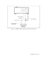
Страница 77: ...Figure 2 17 B R Magnitude Ratio Phase Dynamic Accuracy Test Setup 2 Performance Tests 2 43 ...
Страница 167: ...Figure 5 1 Adjustment Hardware Setup Adjustments 5 5 ...
Страница 186: ...Figure 5 13 Receiver Gain Adjustment Location 5 24 Adjustments ...
Страница 190: ...Figure 5 16 Receiver Flatness Adjustment Setup 1 MHz 5 28 Adjustments ...
Страница 194: ...Figure 5 20 DC Bias Adjustment Setup 2 5 32 Adjustments ...
Страница 196: ...Figure 6 1 Troubleshooting Organization 6 2 Troubleshooting ...
Страница 206: ...Figure 7 1 Power Supply Lines Simplified Block Diagram 7 2 Power Supply Troubleshooting ...
Страница 212: ...Figure 7 5 A1 CPU Connector Locations 7 8 Power Supply Troubleshooting ...
Страница 220: ...Figure 8 1 Digital Control Group Simplified Block Diagram 8 2 Digital Control Troubleshooting ...
Страница 240: ...Figure 10 1 Top View Major Assemblies 10 4 Replaceable Parts ...
Страница 292: ...Table A 2 Manual Changes by Firmware Version Version Make Manual Changes A 2 Manual Changes ...
Страница 303: ...Change 6 Change the Replaceable Parts as following Figure A 10 Top View Major Assemblies Manual Changes A 13 ...
Страница 308: ......
Страница 311: ...Figure B 1 Power Cable Supplied Power Requirement B 3 ...
Страница 312: ......
Страница 342: ......


