


11.
MA
GNITUDE
RA
TIO/PHASE
D
YNAMIC
A
CCURA
CY
TEST
(NA)
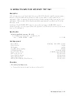
Description
Dynamic
accuracy
is
a
measure
of
ho
w
w
ell
a
receiv
er
measures
the
magnitude
and
phase
comp onen
ts
of
a
signal
as
that
signal
v
aries
in
amplitude
o
v
er
a
sp ecied
dynamic
range.
T
o
measure
the
dynamic
accuracy
,
this
test
applies
a
xed
lev
el
signal
of
020
dBm
to
the
4395A
R
input
(reference
input).
A
t
the
same
time,
it
applies
a
signal
that
v
aries
from
010
dBm
(full
scale
input
lev
el)
to
0110
dBm
to
one
of
the
4395A's
A
or
B
inputs
(test
input).
It
then
measures
the
magnitude
ratio
from
010
dB
to
0100
dB
and
the
phase
of
the
signals.
The
signal
amplitude
at
the
test
input
is
v
aried
b
y
inserting
kno
wn
attenuation
v
alues.
The
measured
magnitude
ratio
v
alues
are
then
compared
to
the
inserted
attenuation's
calibrated
v
alues.
The
phase
dynamic
accuracy
is
measured
at
3
MHz
(where
the
phase
error
con
tribution
b
y
the
individual
attenuator
segmen
ts
is
small
when
compared
to
the
test
limits).
In
this
test,
a
step
attenuator
with
its
VSWR
1.02
and
t
w
o
6
dB
xed
attenuators
with
a
VSWR
1.015
are
used.
Using
these
attenuators
reduces
the
measuremen
t
uncertain
ties
caused
b
y
mismatch
error.
When
they
are
used,
the
measuremen
t
uncertain
ties
listed
in
the
p erformance
test
record
are
v
alid.
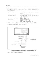
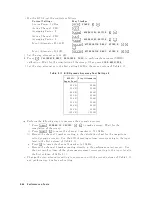
Specification
Magnitude
ratio/phase
dynamic
accuracy
(A/R,
B/R)
Input
Lev
el
(relativ
e
to
full
scale
input
lev
el
0
10
dB)
Magnitude
Ratio
Dynamic
Accuracy
1
Phase
Dynamic
Accuracy
1
0
dB
Input
Level
>
010dB
<60.4
dB
<63
deg
010
dB
Input
Level
060
dB
<60.05
dB
<60.3
deg
060
dB
>
Input
Level
080
dB
<60.3
dB
<61.8
deg
080
dB
>
Input
Level
0100
dB
<63
dB
<618
deg
1:
R
input
level
(B
input
level
for
A/B)
=
full
scale
input
level
0
10
dB,
IFBW
=
10
Hz,
23 65
C,
A
t
the
follo wing
p
oints,
measurement
error
ma
y
exceed
the
sp
ecications:
124.0
MHz,
136.0
MHz,
415.0
MHz
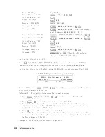
T
est
Equipment
Tw
o-W
a
y
P
o
w
er
Splitter
:
:
:
:
:
:
:
:
:
:
:
:
:
:
:
:
:
:
:
:
:
:
:
:
:
:
:
:
:
:
:
:
:
:
:
:
:
:
:
:
:
:
:
:
:
:
:
:
:
:
:
:
:
:
:
:
:
:
:
11667A
Step
A
tten
uator
1
,
10
dB
Step,
VSWR
1.02
:
:
:
:
:
:
:
:
:
:
:
:
:
:
:
:
:
:
:
:
8496G
Opt.
001
and
H60
A
tten
uator
driv
er
:
:
:
:
:
:
:
:
:
:
:
:
:
:
:
:
:
:
:
:
:
:
:
:
:
:
:
:
:
:
:
:
:
:
:
:
:
:
:
:
:
:
:
:
:
:
:
:
:
:
:
:
:
:
:
:
:
:
:
:
:
:
:
:
:
:
11713A
6
dB
Fixed
A
tten
uation
(tw
o
required)
:
:
:
:
:
:
:
:
:
:
:
:
:
:
:
:
:
:
:
:
:
:
:
:
:
:
:
:
:
:
:
:
:
:
:
:
8491A
Opt.
006
6
dB
Fixed
A
tten
uation,
VSWR
1.015
(tw
o
required)
:
:
:
:
:
:
8491A
Opt.
006
&
Opt.
H60
T
yp e-N
Cable,
61
cm
(three
required)
:
:
:
:
:
:
:
:
:
:
:
:
:
:
:
:
:
:
:
:
:
:
:
:
:
:
:
11500B
or
part
of
11851B
N(m)-N(m)
adapter
:
:
:
:
:
:
:
:
:
:
:
:
:
:
:
:
:
:
:
:
:
:
:
:
:
:
:
:
:
:
:
:
:
:
:
:
:
:
:
:
:
:
:
:
:
:
:
:
:
:
:
:
:
:
:
:
:
PN
1250-1475
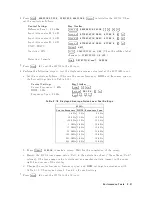
1:
Calibration
v
alues
for
attenuation
settings
of
10
dB
to
100
dB
at
50
MHz
are
required.
2-36
P
erformance
T
ests
Содержание 4395A
Страница 10: ......
Страница 26: ......
Страница 34: ......
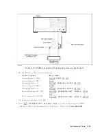
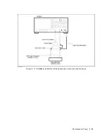
Страница 77: ...Figure 2 17 B R Magnitude Ratio Phase Dynamic Accuracy Test Setup 2 Performance Tests 2 43 ...
Страница 167: ...Figure 5 1 Adjustment Hardware Setup Adjustments 5 5 ...
Страница 186: ...Figure 5 13 Receiver Gain Adjustment Location 5 24 Adjustments ...
Страница 190: ...Figure 5 16 Receiver Flatness Adjustment Setup 1 MHz 5 28 Adjustments ...
Страница 194: ...Figure 5 20 DC Bias Adjustment Setup 2 5 32 Adjustments ...
Страница 196: ...Figure 6 1 Troubleshooting Organization 6 2 Troubleshooting ...
Страница 206: ...Figure 7 1 Power Supply Lines Simplified Block Diagram 7 2 Power Supply Troubleshooting ...
Страница 212: ...Figure 7 5 A1 CPU Connector Locations 7 8 Power Supply Troubleshooting ...
Страница 220: ...Figure 8 1 Digital Control Group Simplified Block Diagram 8 2 Digital Control Troubleshooting ...
Страница 240: ...Figure 10 1 Top View Major Assemblies 10 4 Replaceable Parts ...
Страница 292: ...Table A 2 Manual Changes by Firmware Version Version Make Manual Changes A 2 Manual Changes ...
Страница 303: ...Change 6 Change the Replaceable Parts as following Figure A 10 Top View Major Assemblies Manual Changes A 13 ...
Страница 308: ......
Страница 311: ...Figure B 1 Power Cable Supplied Power Requirement B 3 ...
Страница 312: ......
Страница 342: ......


