


INSPECT
THE
PO
WER
ON
SEQUENCE
Check
the
F
an
T
urn
the
analyzer
p o
w
er
on.
Insp ect
the
fan
on
the
rear
panel.
The
fan
should
b e
rotating
and
audible.
If
case
of
unexpected
results,
c
hec
k
A
C
line
p o
w
er
to
the
analyzer.
Chec
k
the
fuse
(rating
listed
on
the
rear
panel).
Chec
k
the
line
v
oltage
setting.
F
or
setting
the
line
v
oltage,
see
the
Power
R
e
quir
ements
in
App endix
C.
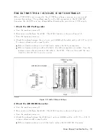
If
the
problem
p ersists,
con
tinue
with
the
Power
Supply
T
r
oublesho
oting
c
hapter.
Check
the
Front
P
anel
LEDs
and
Displays
T
urn
on
the
analyzer
and
w
atch
for
the
follo wing
ev
en
ts
in
this
order:
1.
Beep
is
sounding.
2.
The
4
Ch
1
5
LED
turns
on
and
the
analyzer
displays
In
ternal
T
est
In
Progress
for
sev
eral
seconds.
3.
The
analyzer
displays
the
graticule.
If
case
of
unexpected
results,
con
tinue
with
Digital
Contr
ol
T
r
oublesho
oting
c
hapter.
Check
Error
Message
T
urn
the
analyzer
p o
w
er
on.
Insp ect
the
LCD.
No
error
message
should
b e
display
ed.
If
the
following
status
annotation
app ears
on
the
LCD,
the
A1
CPU
is
susp ected.
Con
tinue
with
the
Digital
Contr
ol
T
r
oublesho
oting
c
hapter.
Svc
(Status
annotation)
If
the
following
error
message
app ears
on
the
LCD,
con
tinue
with
the
INTERNAL
TESTS
F
AILURE
TR
OUBLESHOOTING
in
this
c
hapter.
POWER
ON
TEST
FAILED
These
error
messages
indicate
that
one
of
p o
w
er-on
self
tests
fails.
If
an
other
error
message
app ears,
refer
to
the
Err
or
Messages
in
Messages.
If
the
resp onse
of
fron
t
panel,
GPIB
commands,
or
built-in
FDD
is
unexpected,
con
tinue
with
the
Digital
Contr
ol
T
r
oublesho
oting
c
hapter.
6-4
Troubleshooting
Содержание 4395A
Страница 10: ......
Страница 26: ......
Страница 34: ......
Страница 77: ...Figure 2 17 B R Magnitude Ratio Phase Dynamic Accuracy Test Setup 2 Performance Tests 2 43 ...
Страница 167: ...Figure 5 1 Adjustment Hardware Setup Adjustments 5 5 ...
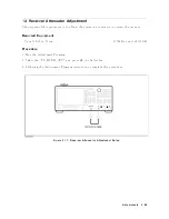
Страница 186: ...Figure 5 13 Receiver Gain Adjustment Location 5 24 Adjustments ...
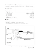
Страница 190: ...Figure 5 16 Receiver Flatness Adjustment Setup 1 MHz 5 28 Adjustments ...
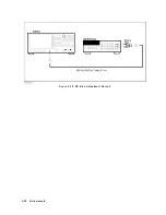
Страница 194: ...Figure 5 20 DC Bias Adjustment Setup 2 5 32 Adjustments ...
Страница 196: ...Figure 6 1 Troubleshooting Organization 6 2 Troubleshooting ...
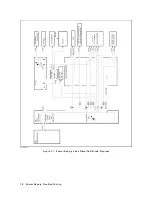
Страница 206: ...Figure 7 1 Power Supply Lines Simplified Block Diagram 7 2 Power Supply Troubleshooting ...
Страница 212: ...Figure 7 5 A1 CPU Connector Locations 7 8 Power Supply Troubleshooting ...
Страница 220: ...Figure 8 1 Digital Control Group Simplified Block Diagram 8 2 Digital Control Troubleshooting ...
Страница 240: ...Figure 10 1 Top View Major Assemblies 10 4 Replaceable Parts ...
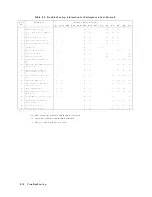
Страница 292: ...Table A 2 Manual Changes by Firmware Version Version Make Manual Changes A 2 Manual Changes ...
Страница 303: ...Change 6 Change the Replaceable Parts as following Figure A 10 Top View Major Assemblies Manual Changes A 13 ...
Страница 308: ......
Страница 311: ...Figure B 1 Power Cable Supplied Power Requirement B 3 ...
Страница 312: ......
Страница 342: ......


