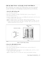


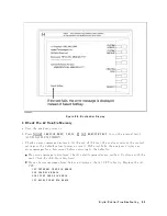


Figure
8-6.
Bootloader
Display
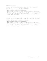
4.
Check
the
A1
V
olatile
Memory
a.
T
urn
the
analyzer
p o
w
er
on.
b.
Press
4
System
5,
NNNNNNNNNNNNNNNNNNNNNNNNNNNNNNNNNNNNNN
SERVICE
MENU
,
NNNNNNNNNNNNNNNNN
TESTS
,
4
2
5,
4
x1
5,
NNNNNNNNNNNNNNNNNNNNNNNNNNNNNNNNNNNNNN
EXECUTE
TEST
to
run
the
in
ternal
test
2:
A1
V
OLA
TILE
MEMOR
Y.
c.
Chec
k
no
error
message
display
ed.
A
t
the
end
of
this
test,
the
analyzer
returns
the
con
trol
settings
to
the
default
v
alues
(p o
w
er
on
reset).
If
the
test
fails,
the
analyzer
displays
an
error
messages
for
a
few
second
b efore
returning
to
the
defaults.
If
no
error
message
is
display
ed,
the
A1
v
olatile
memories
are
v
eried.
Con
tin
ue
with
the
next
Che
ck
the
A30
F
r
ont
Keyb
o
ar
d.
If
one
of
error
messages
listed
b elow
is
display
ed,
the
A1
CPU
is
fault
y
.
Replace
the
A1
CPU.
CPU
INTERNAL
SRAM
R/W
ERROR
DSP
SRAM
R/W
ERROR
DUAL
PORT
SRAM
R/W
ERROR
CPU
BACKUP
SRAM
R/W
ERROR
Digital
Control
Troubleshooting
8-9
Содержание 4395A
Страница 10: ......
Страница 26: ......
Страница 34: ......
Страница 77: ...Figure 2 17 B R Magnitude Ratio Phase Dynamic Accuracy Test Setup 2 Performance Tests 2 43 ...
Страница 167: ...Figure 5 1 Adjustment Hardware Setup Adjustments 5 5 ...
Страница 186: ...Figure 5 13 Receiver Gain Adjustment Location 5 24 Adjustments ...
Страница 190: ...Figure 5 16 Receiver Flatness Adjustment Setup 1 MHz 5 28 Adjustments ...
Страница 194: ...Figure 5 20 DC Bias Adjustment Setup 2 5 32 Adjustments ...
Страница 196: ...Figure 6 1 Troubleshooting Organization 6 2 Troubleshooting ...
Страница 206: ...Figure 7 1 Power Supply Lines Simplified Block Diagram 7 2 Power Supply Troubleshooting ...
Страница 212: ...Figure 7 5 A1 CPU Connector Locations 7 8 Power Supply Troubleshooting ...
Страница 220: ...Figure 8 1 Digital Control Group Simplified Block Diagram 8 2 Digital Control Troubleshooting ...
Страница 240: ...Figure 10 1 Top View Major Assemblies 10 4 Replaceable Parts ...
Страница 292: ...Table A 2 Manual Changes by Firmware Version Version Make Manual Changes A 2 Manual Changes ...
Страница 303: ...Change 6 Change the Replaceable Parts as following Figure A 10 Top View Major Assemblies Manual Changes A 13 ...
Страница 308: ......
Страница 311: ...Figure B 1 Power Cable Supplied Power Requirement B 3 ...
Страница 312: ......
Страница 342: ......


