


If
the
v
oltmeter
reading
is
within
the
limits,
the
A50
+5
VD
p o
w
er
supply
is
v
eried.
T
urn
the
analyzer
p o
w
er
o
and
reconnect
the
cable
to
the
A50J3.
Then
con
tinue
with
the
next
Disc
onne
ct
Cables
on
the
A1
CPU
section.
3.
Disconnect
Cables
on
the
A1
CPU
a.
T
urn
the
analyzer
p o
w
er
o.
b.
Disconnect
cables
from
the
A1
CPU's
connectors,
J10,
J11,
J12,
J13,
J14,
J15,
and
J17.
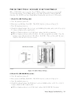
The
connector
lo
cations
are
sho
wn
in
Figure
7-7
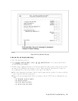
Figure
7-7.
A1
CPU
Connector
Locations
c.
T
urn
the
analyzer
p o
w
er
on.
Lo ok
at
the
A1
+5
VD
LED.
If
the
LED
is
still
o,
the
A1
CPU
is
probably
faulty
.
Replace
the
A1
CPU.
If
the
LED
go
es
on,
the
A1
CPU
is
v
eried.
Con
tinue
with
the
next
step.
d.
T
urn
the
analyzer
p o
w
er
o.
Reconnect
the
cable
to
the
A1J10.
T
urn
the
analyzer
p o
w
er
on.
Lo ok
at
the
A1
+5
VD
LED.
If
the
+5
VD
LED
go
es
out,
the
problem
may
b e
in
the
analog
assem
blies.
Con
tinue
with
the
next
R
emove
Assemblies
.
If
the
+
5
VD
LED
is
still
on,
con
tinue
with
the
next
step.
e.
Reconnect
one
of
the
disconnected
cables
to
its
connector
at
a
time.
T
urn
the
analyzer
p o
w
er
on
after
eac
h
cable
is
connected.
The
assem
bly
related
with
the
cable
turning
the
+5
VD
LED
o
is
probably
faulty
.
Replace
the
assem
bly
.
7-10
P
o
w
er
Supply
Troubleshooting
Содержание 4395A
Страница 10: ......
Страница 26: ......
Страница 34: ......
Страница 77: ...Figure 2 17 B R Magnitude Ratio Phase Dynamic Accuracy Test Setup 2 Performance Tests 2 43 ...
Страница 167: ...Figure 5 1 Adjustment Hardware Setup Adjustments 5 5 ...
Страница 186: ...Figure 5 13 Receiver Gain Adjustment Location 5 24 Adjustments ...
Страница 190: ...Figure 5 16 Receiver Flatness Adjustment Setup 1 MHz 5 28 Adjustments ...
Страница 194: ...Figure 5 20 DC Bias Adjustment Setup 2 5 32 Adjustments ...
Страница 196: ...Figure 6 1 Troubleshooting Organization 6 2 Troubleshooting ...
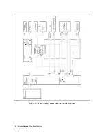
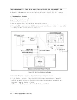
Страница 206: ...Figure 7 1 Power Supply Lines Simplified Block Diagram 7 2 Power Supply Troubleshooting ...
Страница 212: ...Figure 7 5 A1 CPU Connector Locations 7 8 Power Supply Troubleshooting ...
Страница 220: ...Figure 8 1 Digital Control Group Simplified Block Diagram 8 2 Digital Control Troubleshooting ...
Страница 240: ...Figure 10 1 Top View Major Assemblies 10 4 Replaceable Parts ...
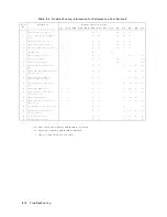
Страница 292: ...Table A 2 Manual Changes by Firmware Version Version Make Manual Changes A 2 Manual Changes ...
Страница 303: ...Change 6 Change the Replaceable Parts as following Figure A 10 Top View Major Assemblies Manual Changes A 13 ...
Страница 308: ......
Страница 311: ...Figure B 1 Power Cable Supplied Power Requirement B 3 ...
Страница 312: ......
Страница 342: ......


