


INSPECT
THE
REAR
P
ANEL
FEA
TURE
If
the
analyzer
is
op erating
unexp
ectedly
after
these
c
hec
ks
are
v
eried,
con
tinue
with
Digital
Contr
ol
T
r
oublesho
oting
c
hapter.
Check
the
GPIB
Interface
If
the
unexpected
op erations
app ear
when
con
trolling
the
analyzer
with
an
external
con
troller,
p erform
the
follo wing
c
hec
ks
to
v
erify
the
problem
is
not
with
the
con
troller.
GPIB
in
terface
hardw
are
m
ust
b e
installed
in
the
con
troller,
see
the
man
uals
of
the
con
troller
and
the
BASIC
system.
I/O
and
GPIB
binaries
loaded,
see
the
man
uals
of
the
BASIC
system.
Select
co de,
see
the
man
uals
of
the
BASIC
system.
GPIB
cables,
see
the
man
uals
of
the
BASIC
system.
Programming
syn
tax,
see
the
man
uals
of
the
BASIC
system.
Check
the
P
arallel
Interface
See
the
T
o
section
at
the
Chapter
8,
Analyzing
the
Measuremen
t
Results,
of
the
4395A
User's
Guide,
and
make
a
hardcop
y
of
the
display
.
Check
the
mini
DIN
Keyboard
Connector
See
the
Connecting
a
Keyb oard
at
the
Chapter
1,
Installation
Guide,
of
the
4395A
User's
Guide.
Troubleshooting
6-5
Содержание 4395A
Страница 10: ......
Страница 26: ......
Страница 34: ......
Страница 77: ...Figure 2 17 B R Magnitude Ratio Phase Dynamic Accuracy Test Setup 2 Performance Tests 2 43 ...
Страница 167: ...Figure 5 1 Adjustment Hardware Setup Adjustments 5 5 ...
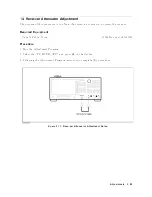
Страница 186: ...Figure 5 13 Receiver Gain Adjustment Location 5 24 Adjustments ...
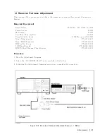
Страница 190: ...Figure 5 16 Receiver Flatness Adjustment Setup 1 MHz 5 28 Adjustments ...
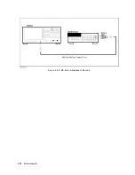
Страница 194: ...Figure 5 20 DC Bias Adjustment Setup 2 5 32 Adjustments ...
Страница 196: ...Figure 6 1 Troubleshooting Organization 6 2 Troubleshooting ...
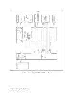
Страница 206: ...Figure 7 1 Power Supply Lines Simplified Block Diagram 7 2 Power Supply Troubleshooting ...
Страница 212: ...Figure 7 5 A1 CPU Connector Locations 7 8 Power Supply Troubleshooting ...
Страница 220: ...Figure 8 1 Digital Control Group Simplified Block Diagram 8 2 Digital Control Troubleshooting ...
Страница 240: ...Figure 10 1 Top View Major Assemblies 10 4 Replaceable Parts ...
Страница 292: ...Table A 2 Manual Changes by Firmware Version Version Make Manual Changes A 2 Manual Changes ...
Страница 303: ...Change 6 Change the Replaceable Parts as following Figure A 10 Top View Major Assemblies Manual Changes A 13 ...
Страница 308: ......
Страница 311: ...Figure B 1 Power Cable Supplied Power Requirement B 3 ...
Страница 312: ......
Страница 342: ......


