Error
Messages
in
Alphabetical
Order
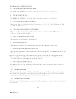
120
NO
MEMOR
Y
TRACE
DISPLA
YED
The
NNNNNNNNNNNNNNNNNNNNNNNNNNNNNNNNNNNNNNNNNNNNNNNNNNNNNNNN
SCALE
FOR
[MEMORY]
is
selected
when
the
memory
trace
is
not
display
ed.
94
NO
MEMOR
Y
TRACE
The
NNNNNNNNNNNNNNNNNNNNNNNNNNNNNNNNNNNNNNNNNNNNNNNNNNNNNNNN
MARKER
ON
[MEMORY]
is
selected
when
the
memory
trace
is
not
display
ed.
113
NO
ST
A
TE/DA
T
A
FILES
ON
DISK
There
are
no
les
on
the
exible
disk
with
extensions,
\ _D "
or
\ _S "
for
LIF
format,
or
\ STA "
or
\ .DTA "
for
DOS
format.
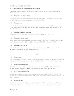
116
NO
ST
A
TE/DA
T
A
FILES
ON
MEMOR
Y
There
are
no
les
on
the
memory
disk
with
extensions,
\ _D "
or
\ _S "
for
LIF
format,
or
\ .STA "
or
\ .DTA "
for
DOS
format.
184
NOT
ALLO
WED
IN
SV
C
MODE
The
op eration
is
not
allo
w
ed
in
service
mo
de.
55
NOT
ENOUGH
D
A
T
A
The
amoun
t
of
data
sen
t
to
the
analyzer
is
less
than
that
exp ected
( GPIB
only
).
14
NOT
V
ALID
FOR
PRESENT
TEST
SET
The
calibration
requested
is
inconsisten
t
with
the
test
set
presen
t.
This
message
o ccurs
in
the
follo
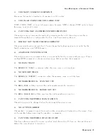
wing
situations:
A
full
2-p ort
calibration
is
requested
with
a
test
set
other
than
an
S-parameter
test
set.
A
one-path
2-p ort
calibration
is
requested
with
an
S-parameter
test
set
(this
pro cedure
is
t
ypically
used
with
a
transmission/reection
test
set).
34
NO
V
ALID
MEMOR
Y
TRACE
If
a
memory
trace
is
to
b e
display
ed
or
otherwise
used,
a
data
trace
m
ust
rst
b e
stored
to
memory
.
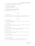
0120
Numeric
data
error
This
error,
as
w
ell
as
errors
0121
through
0129,
are
generated
when
parsing
a
data
elemen
t
that
app ears
to
b e
n
umeric,
including
the
nondecimal
n
umeric
t
yp es.
This
particular
error
message
is
used
if
the
analyzer
cannot
detect
a
more
sp ecic
error.
0128
Numeric
data
not
allo
w
ed
A
legal
n
umeric
data
elemen
t
w
as
receiv
ed,
but
the
analyzer
do es
not
accept
it
in
this
p osition
for
a
header.
O
Messages-10
Содержание 4395A
Страница 10: ......
Страница 26: ......
Страница 34: ......
Страница 77: ...Figure 2 17 B R Magnitude Ratio Phase Dynamic Accuracy Test Setup 2 Performance Tests 2 43 ...
Страница 167: ...Figure 5 1 Adjustment Hardware Setup Adjustments 5 5 ...
Страница 186: ...Figure 5 13 Receiver Gain Adjustment Location 5 24 Adjustments ...
Страница 190: ...Figure 5 16 Receiver Flatness Adjustment Setup 1 MHz 5 28 Adjustments ...
Страница 194: ...Figure 5 20 DC Bias Adjustment Setup 2 5 32 Adjustments ...
Страница 196: ...Figure 6 1 Troubleshooting Organization 6 2 Troubleshooting ...
Страница 206: ...Figure 7 1 Power Supply Lines Simplified Block Diagram 7 2 Power Supply Troubleshooting ...
Страница 212: ...Figure 7 5 A1 CPU Connector Locations 7 8 Power Supply Troubleshooting ...
Страница 220: ...Figure 8 1 Digital Control Group Simplified Block Diagram 8 2 Digital Control Troubleshooting ...
Страница 240: ...Figure 10 1 Top View Major Assemblies 10 4 Replaceable Parts ...
Страница 292: ...Table A 2 Manual Changes by Firmware Version Version Make Manual Changes A 2 Manual Changes ...
Страница 303: ...Change 6 Change the Replaceable Parts as following Figure A 10 Top View Major Assemblies Manual Changes A 13 ...
Страница 308: ......
Страница 311: ...Figure B 1 Power Cable Supplied Power Requirement B 3 ...
Страница 312: ......
Страница 342: ......


