
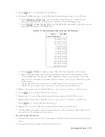


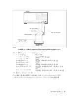


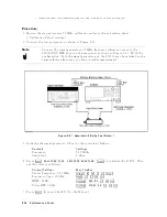


Figure
2-18.
A/R
Magnitude
Ratio/Phase
Frequency
Response
T
est
Setup
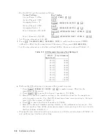
b.
Set
the
4395A
con
trols
as
follows:
Con
trol
Settings
Key
Strok
es
Active
Channel:
CH
1
4
Ch
1
5
Input
P
ort:
A/R
4
Meas
5,
NNNNNNNNNNN
A/R
F
ormat:
LOG
MA
G
4
F
ormat
5,
NNNNNNNNNNNNNNNNNNNNNNN
LOG
MAG
Active
Channel:
CH
2
4
Ch
2
5
Input
P
ort:
A/R
4
Meas
5,
NNNNNNNNNNN
A/R
F
ormat:
PHASE
4
F
ormat
5,
NNNNNNNNNNNNNNNNN
PHASE
Start
F
requency:
1
MHz
4
Start
5,
4
1
5,
4
M/
5
Stop
F
requency:
500
MHz
4
Stop
5,
4
5
5,
4
0
5,
4
0
5,
4
M/
5
Num
b er
of
P
oints:
500
4
Sw
eep
5,
NNNNNNNNNNNNNNNNNNNNNNNNNNNNNNNNNNNNNNNNNNNNNNNNNN
NUMBER
of
POINTS
,
4
5
5,
4
0
5,
4
0
5,
4
x1
5
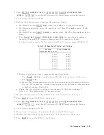
c.
Press
4
T
rigger
5,
NNNNNNNNNNNNNNNNNNNN
SINGLE
to
make
a
sw
eep.
W
ait
for
the
completion
of
the
sw
eep.
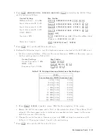
d.
Set
the
4395A
con
trols
as
follows:
Con
trol
Settings
Key
Strok
es
Active
Channel:
CH
1
4
Ch
1
5
Data !Memory
4
Displa
y
5,
NNNNNNNNNNNNNNNNNNNNNNNNNNNNNNNNNNNNNN
DATA !MEMORY
Active
Channel:
CH
2
4
Ch
2
5
Data !Memory
4
Displa
y
5,
NNNNNNNNNNNNNNNNNNNNNNNNNNNNNNNNNNNNNN
DATA !MEMORY
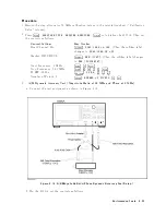
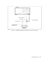
e.
Rev
erse
the
cable
connections
of
the
4395A
A
and
R
inputs
as
sho
wn
in
setup
2
of
Figure
2-18.
f.
Press
4
T
rigger
5,
NNNNNNNNNNNNNNNNNNNN
SINGLE
to
make
a
sw
eep.
W
ait
for
the
completion
of
the
sw
eep.
g.
Set
the
4395A
con
trols
as
follows:
Con
trol
Settings
Key
Strok
es
2-46
P
erformance
T
ests
Содержание 4395A
Страница 10: ......
Страница 26: ......
Страница 34: ......
Страница 77: ...Figure 2 17 B R Magnitude Ratio Phase Dynamic Accuracy Test Setup 2 Performance Tests 2 43 ...
Страница 167: ...Figure 5 1 Adjustment Hardware Setup Adjustments 5 5 ...
Страница 186: ...Figure 5 13 Receiver Gain Adjustment Location 5 24 Adjustments ...
Страница 190: ...Figure 5 16 Receiver Flatness Adjustment Setup 1 MHz 5 28 Adjustments ...
Страница 194: ...Figure 5 20 DC Bias Adjustment Setup 2 5 32 Adjustments ...
Страница 196: ...Figure 6 1 Troubleshooting Organization 6 2 Troubleshooting ...
Страница 206: ...Figure 7 1 Power Supply Lines Simplified Block Diagram 7 2 Power Supply Troubleshooting ...
Страница 212: ...Figure 7 5 A1 CPU Connector Locations 7 8 Power Supply Troubleshooting ...
Страница 220: ...Figure 8 1 Digital Control Group Simplified Block Diagram 8 2 Digital Control Troubleshooting ...
Страница 240: ...Figure 10 1 Top View Major Assemblies 10 4 Replaceable Parts ...
Страница 292: ...Table A 2 Manual Changes by Firmware Version Version Make Manual Changes A 2 Manual Changes ...
Страница 303: ...Change 6 Change the Replaceable Parts as following Figure A 10 Top View Major Assemblies Manual Changes A 13 ...
Страница 308: ......
Страница 311: ...Figure B 1 Power Cable Supplied Power Requirement B 3 ...
Страница 312: ......
Страница 342: ......


