


9.
En
ter
the
serial
n
um
b er
of
the
4395A
exactly
.
F
or
example,
JP1E00123
10.
Mark
installed
options
of
the
4395A.
The
installed
options
can
b e
conrmed
on
the
rear
pannel
of
the
4395A,
or
when
y
ou
turn
the
4395A
ON,
y
ou
can
see
the
installed
options
b efore
the
4395A
starts
measuremen
t.
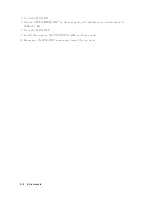
11.
Press
NNNNNNNNNNNNNNNNNNNNNNNNNNNNN
NEXT
STEP
.
Figure
5-2.
List
Bo
x
Note
\WRITE
ID"
is
used
to
write
required
iden
tication
data
in
to
the
in
ternal
memory
of
the
4395A.
\INIT
CAL"
is
used
to
delete
correction
constan
ts.
See
Post
R
ep
air
Pr
o
c
e
dur
e
for
details.
Adjustments
5-7
Содержание 4395A
Страница 10: ......
Страница 26: ......
Страница 34: ......
Страница 77: ...Figure 2 17 B R Magnitude Ratio Phase Dynamic Accuracy Test Setup 2 Performance Tests 2 43 ...
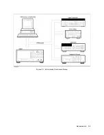
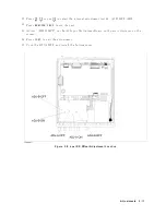
Страница 167: ...Figure 5 1 Adjustment Hardware Setup Adjustments 5 5 ...
Страница 186: ...Figure 5 13 Receiver Gain Adjustment Location 5 24 Adjustments ...
Страница 190: ...Figure 5 16 Receiver Flatness Adjustment Setup 1 MHz 5 28 Adjustments ...
Страница 194: ...Figure 5 20 DC Bias Adjustment Setup 2 5 32 Adjustments ...
Страница 196: ...Figure 6 1 Troubleshooting Organization 6 2 Troubleshooting ...
Страница 206: ...Figure 7 1 Power Supply Lines Simplified Block Diagram 7 2 Power Supply Troubleshooting ...
Страница 212: ...Figure 7 5 A1 CPU Connector Locations 7 8 Power Supply Troubleshooting ...
Страница 220: ...Figure 8 1 Digital Control Group Simplified Block Diagram 8 2 Digital Control Troubleshooting ...
Страница 240: ...Figure 10 1 Top View Major Assemblies 10 4 Replaceable Parts ...
Страница 292: ...Table A 2 Manual Changes by Firmware Version Version Make Manual Changes A 2 Manual Changes ...
Страница 303: ...Change 6 Change the Replaceable Parts as following Figure A 10 Top View Major Assemblies Manual Changes A 13 ...
Страница 308: ......
Страница 311: ...Figure B 1 Power Cable Supplied Power Requirement B 3 ...
Страница 312: ......
Страница 342: ......


