


POWER
FAILED
ON
PostRegHot
This
indicates
A2
p o
w
er
supplies,
+15
V,
+8.5
V,
+5.3
V,
+5
V,
-5
V,
-15
V,
are
sh
ut
do
wn
due
to
to
o
hot
heat
sink
on
A2
p ost-regulator.
Co
ol
do
wn
the
analyzer
for
ab out
30
min
utes.
Then
turn
the
analyzer
p o
w
er
on.
If
this
message
is
still
display
ed,
replace
A2
p ost-regulator.
PHASE
LOCK
LOOP
UNLOCKED
This
indicates
one
or
some
of
PLLs
(phase
lo
c
k
lo
ops)
in
the
oscillators
is
not
w
orking
prop erly
.
These
oscillators
are
c
hec
k
ed
in
the
in
ternal
test
0:
ALL
INT.
Con
tin
ue
with
the
next
Che
ck
the
Power
On
Selftest
in
where
the
ALL
INT
test
is
executed.
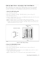
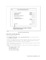
3.
Check
the
A1
DRAM
and
Flash
Memory
The
A1
DRAM
and
ash
memory
are
tested
on
the
sequence
to
access
the
b o otloader
men
u.
P
erform
the
following
pro cedure
to
v
erify
the
A1
DRAM
and
ash
memory
.
a.
T
urn
the
analyzer
p o
w
er
o.
b.
Push
t
w
o
k
eys
4
Start
5
and
4
Preset
5.
With
k
eeping
the
t
w
o
k
eys
pushed
do
wn,
turn
the
analyzer
p o
w
er
on.
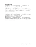
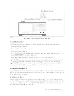
c.
W
ait
for
the
display
sho
wn
in
Figure
8-6
app ears
on
the
LCD.
d.
Chec
k
no
error
message
display
ed
on
the
LCD.
If
no
error
message
is
display
ed,
the
A1
DRAM
and
ash
memories
are
v
eried.
Con
tinue
with
the
next
Che
ck
the
A1
V
olatile
Memory
.
If
an
error
message
is
display
ed
or
the
display
sho
wn
in
Figure
8-6
do es
not
app ear,
the
A1
CPU
is
probably
fault
y
.
Replace
the
A1
CPU.
8-8
Digital
Control
Troubleshooting
Содержание 4395A
Страница 10: ......
Страница 26: ......
Страница 34: ......
Страница 77: ...Figure 2 17 B R Magnitude Ratio Phase Dynamic Accuracy Test Setup 2 Performance Tests 2 43 ...
Страница 167: ...Figure 5 1 Adjustment Hardware Setup Adjustments 5 5 ...
Страница 186: ...Figure 5 13 Receiver Gain Adjustment Location 5 24 Adjustments ...
Страница 190: ...Figure 5 16 Receiver Flatness Adjustment Setup 1 MHz 5 28 Adjustments ...
Страница 194: ...Figure 5 20 DC Bias Adjustment Setup 2 5 32 Adjustments ...
Страница 196: ...Figure 6 1 Troubleshooting Organization 6 2 Troubleshooting ...
Страница 206: ...Figure 7 1 Power Supply Lines Simplified Block Diagram 7 2 Power Supply Troubleshooting ...
Страница 212: ...Figure 7 5 A1 CPU Connector Locations 7 8 Power Supply Troubleshooting ...
Страница 220: ...Figure 8 1 Digital Control Group Simplified Block Diagram 8 2 Digital Control Troubleshooting ...
Страница 240: ...Figure 10 1 Top View Major Assemblies 10 4 Replaceable Parts ...
Страница 292: ...Table A 2 Manual Changes by Firmware Version Version Make Manual Changes A 2 Manual Changes ...
Страница 303: ...Change 6 Change the Replaceable Parts as following Figure A 10 Top View Major Assemblies Manual Changes A 13 ...
Страница 308: ......
Страница 311: ...Figure B 1 Power Cable Supplied Power Requirement B 3 ...
Страница 312: ......
Страница 342: ......


