


j.
Press
NNNNNNNNNNNNNNNNNNNN
SHORTS
,
NNNNNNNNNNNNNNNNNNNNNNNNNNNNN
SHORT
(M)
.
W
ait
un
til
a
b eep
sounds.
Then
press
NNNNNNNNNNNNNNNNNNNNNNNNNNNNNNNNNNN
DONE:SHORTS
.
k.
Remo
v
e
the
short
from
the
test
p ort
cable
and
connect
a
t
yp e
N(f
)
50
load
to
the
test
p ort
cable.
l.
Press
NNNNNNNNNNNNNN
LOAD
.
W
ait
un
til
a
b eep
sounds.
m.
Press
NNNNNNNNNNNNNNNNNNNNNNNNNNNNNNNNNNNNNNNNNNNNNNN
DONE:1-PORT
CAL
to
complete
the
calibration
sequence.
n.
Remo
v
e
the
t
yp e
N(f
)
50
load
from
the
test
p ort
cable
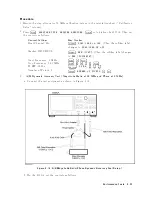
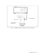
4.
Connect
the
test
p ort
cable
to
the
4395A
R
input.
5.
On
the
net
w
ork
analyzer,
press
4
MENU
5,
NNNNNNNNNNNNNNNNNNNNNNNNNNNNNNNNNNNNNN
TRIGGER
MENU
,
NNNNNNNNNNNNNNNNNNNN
SINGLE
to
make
a
sw
eep.
W
ait
for
the
completion
of
the
sw
eep.
6.
On
the
net
w
ork
analyzer,
press
4
MKR
F
CTN
5,
NNNNNNNNNNNNNNNNNNNNNNNNNNNNNNNNNNNNNNNNNNNNNNNNNN
MKR
SEARCH
[OFF]
,
NNNNNNNNNNN
MAX
to
mov
e
the
marker
to
the
maxim
um
p oint
on
the
trace.
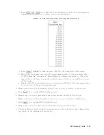
7.
Record
the
net
w
ork
analyzer's
marker
reading
(with
an
opp osite
sign)
in
the
p erformance
test
record
(\T
est
Result"
column).
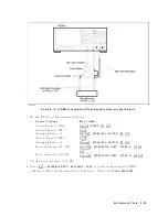
8.
Remo
v
e
the
test
p ort
cable
from
the
4395A
R
input
and
connect
it
to
the
A
input.
9.
On
the
net
w
ork
analyzer,
press
4
MENU
5,
NNNNNNNNNNNNNNNNNNNNNNNNNNNNNNNNNNNNNN
TRIGGER
MENU
,
NNNNNNNNNNNNNNNNNNNN
SINGLE
to
make
a
sw
eep.
W
ait
for
the
completion
of
the
sw
eep.
10.
On
the
net
w
ork
analyzer,
press
4
MKR
F
CTN
5,
NNNNNNNNNNNNNNNNNNNNNNNNNNNNNNNNNNNNNNNNNNNNNNNNNN
MKR
SEARCH
[OFF]
,
NNNNNNNNNNN
MAX
to
mov
e
the
marker
to
the
maxim
um
p oint
on
the
trace.
11.
Record
the
net
w
ork
analyzer's
marker
reading
(with
an
opp osite
sign)
in
the
p erformance
test
record
(\T
est
Result"
column).
12.
Remo
v
e
the
test
p ort
cable
from
the
4395A
A
input
and
connect
it
to
the
B
input.
13.
On
the
net
w
ork
analyzer,
press
4
MENU
5,
NNNNNNNNNNNNNNNNNNNNNNNNNNNNNNNNNNNNNN
TRIGGER
MENU
,
NNNNNNNNNNNNNNNNNNNN
SINGLE
to
make
a
sw
eep.
W
ait
for
the
completion
of
the
sw
eep.
14.
On
the
net
w
ork
analyzer,
press
4
MKR
F
CTN
5,
NNNNNNNNNNNNNNNNNNNNNNNNNNNNNNNNNNNNNNNNNNNNNNNNNN
MKR
SEARCH
[OFF]
,
NNNNNNNNNNN
MAX
to
mov
e
the
marker
to
the
maxim
um
p oint
on
the
trace.
15.
Record
the
net
w
ork
analyzer's
marker
reading
(with
an
opp osite
sign)
in
the
p erformance
test
record
(\T
est
Result"
column).
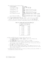
16.
On
the
net
w
ork
analyzer,
p erform
the
follo wing
steps
to
set
the
net
w
ork
analyzer
con
trols
to
measure
the
return
loss
from
100
MHz
to
500
MHz.
a.
Press
4
Preset
5
to
initialize
the
net
w
ork
analyzer.
b.
Press
4
Start
5,
4
1
5,
4
0
5,
4
0
5,
4
M/
5.
c.
Press
4
Stop
5,
4
5
5,
4
0
5,
4
0
5,
4
M/
5.
d.
Press
4
Menu
5,
NNNNNNNNNNNNNNNNNNNNNNNNNNNNNNNNNNNNNNNNNNNNNNN
SWEEP
TYPE
MENU
,
NNNNNNNNNNNNNNNNNNNNNNNNNN
LOG
FREQ
e.
Press
4
Avg
5,
NNNNNNNNNNNNNNNNN
IF
BW
,
4
1
5,
4
0
5,
4
0
5,
4
x1
5.
f.
Press
4
CAL
5,
NNNNNNNNNNNNNNNNNNNNNNNNNNNNNNNNNNNNNNNNN
CAL
KIT
[7mm]
,
NNNNNNNNNNNNNNNNN
N
50
,
NNNNNNNNNNNNNNNNNNNN
RETURN
,
NNNNNNNNNNNNNNNNNNNNNNNNNNNNNNNNNNNNNNNNNNNNNNNNNN
CALIBRATION
MENU
,
NNNNNNNNNNNNNNNNNNNNNNNNNNNNNNNN
S11
1-PORT
to
initiate
a
calibration.
g.
Connect
a
t
yp e
N(f
)
op en
to
the
end
of
the
test
p ort
cable.
h.
Press
NNNNNNNNNNNNNNNNNNNNNNNNNNNNNNNNNNN
(S11):OPENS
,
NNNNNNNNNNNNNNNNNNNNNNNNNN
OPEN
(M)
.
W
ait
un
til
a
b eep
sounds.
Then
press
NNNNNNNNNNNNNNNNNNNNNNNNNNNNNNNN
DONE:OPENS
.
i.
Remo
v
e
the
op en
from
the
test
p ort
cable
and
connect
a
t
yp e
N(f
)
short
to
the
test
p ort
cable.
j.
Press
NNNNNNNNNNNNNNNNNNNN
SHORTS
,
NNNNNNNNNNNNNNNNNNNNNNNNNNNNN
SHORT
(M)
.
W
ait
un
til
a
b eep
sounds.
Then
press
NNNNNNNNNNNNNNNNNNNNNNNNNNNNNNNNNNN
DONE:SHORTS
.
P
erformance
T
ests
2-29
Содержание 4395A
Страница 10: ......
Страница 26: ......
Страница 34: ......
Страница 77: ...Figure 2 17 B R Magnitude Ratio Phase Dynamic Accuracy Test Setup 2 Performance Tests 2 43 ...
Страница 167: ...Figure 5 1 Adjustment Hardware Setup Adjustments 5 5 ...
Страница 186: ...Figure 5 13 Receiver Gain Adjustment Location 5 24 Adjustments ...
Страница 190: ...Figure 5 16 Receiver Flatness Adjustment Setup 1 MHz 5 28 Adjustments ...
Страница 194: ...Figure 5 20 DC Bias Adjustment Setup 2 5 32 Adjustments ...
Страница 196: ...Figure 6 1 Troubleshooting Organization 6 2 Troubleshooting ...
Страница 206: ...Figure 7 1 Power Supply Lines Simplified Block Diagram 7 2 Power Supply Troubleshooting ...
Страница 212: ...Figure 7 5 A1 CPU Connector Locations 7 8 Power Supply Troubleshooting ...
Страница 220: ...Figure 8 1 Digital Control Group Simplified Block Diagram 8 2 Digital Control Troubleshooting ...
Страница 240: ...Figure 10 1 Top View Major Assemblies 10 4 Replaceable Parts ...
Страница 292: ...Table A 2 Manual Changes by Firmware Version Version Make Manual Changes A 2 Manual Changes ...
Страница 303: ...Change 6 Change the Replaceable Parts as following Figure A 10 Top View Major Assemblies Manual Changes A 13 ...
Страница 308: ......
Страница 311: ...Figure B 1 Power Cable Supplied Power Requirement B 3 ...
Страница 312: ......
Страница 342: ......


