


1.
P
erform
an
S11
1-p ort
calibration
on
a
p ort
using
the
go
o d
short
and
op en.
Then
press
4
F
ormat
5,
NNNNNNNNNNNNNNNNNNNNNNNNNNNNNNNNNNN
SMITH
CHART
to
view
the
devices
in
Smith
c
hart
format.
2.
Connect
the
go
o d
short
to
the
calibrated
p ort.
Press
4
Scale
Ref
5,
NNNNNNNNNNNNNNNNNNNNNNNNNNNNNNNNNNNNNNNNNNNNNNN
ELEC
DELAY
MENU
,
NNNNNNNNNNNNNNNNNNNNNNNNNNNNNNNNNNNNNNNNNNNNNNNNNN
ELECTRICAL
DELAY
and
turn
the
RPG
to
en
ter
enough
electrical
dela
y
so
that
the
trace
app ears
as
a
dot
at
the
left
side
of
the
circle.
Replace
the
go
o d
short
with
the
questionable
short
at
the
p ort.
The
trace
of
the
questionable
short
should
app ear
v
ery
similar
to
the
kno
wn
go
o d
short.
3.
Connect
the
go
o d
op en
to
the
calibrated
p ort.
Press
4
Scale
Ref
5,
NNNNNNNNNNNNNNNNNNNNNNNNNNNNNNNNNNNNNNNNNNNNNNN
ELEC
DELAY
MENU
,
NNNNNNNNNNNNNNNNNNNNNNNNNNNNNNNNNNNNNNNNNNNNNNNNNN
ELECTRICAL
DELAY
and
turn
the
RPG
to
en
ter
enough
electrical
dela
y
so
that
the
trace
app ears
as
a
dot
at
the
right
side
of
the
circle.
Replace
the
go
o d
op en
with
the
questionable
op en
at
the
p ort.
The
trace
of
the
questionable
op en
should
app ear
v
ery
similar
to
the
kno
wn
go
o d
op en.
9-6
Accessories
Troubleshooting
Содержание 4395A
Страница 10: ......
Страница 26: ......
Страница 34: ......
Страница 77: ...Figure 2 17 B R Magnitude Ratio Phase Dynamic Accuracy Test Setup 2 Performance Tests 2 43 ...
Страница 167: ...Figure 5 1 Adjustment Hardware Setup Adjustments 5 5 ...
Страница 186: ...Figure 5 13 Receiver Gain Adjustment Location 5 24 Adjustments ...
Страница 190: ...Figure 5 16 Receiver Flatness Adjustment Setup 1 MHz 5 28 Adjustments ...
Страница 194: ...Figure 5 20 DC Bias Adjustment Setup 2 5 32 Adjustments ...
Страница 196: ...Figure 6 1 Troubleshooting Organization 6 2 Troubleshooting ...
Страница 206: ...Figure 7 1 Power Supply Lines Simplified Block Diagram 7 2 Power Supply Troubleshooting ...
Страница 212: ...Figure 7 5 A1 CPU Connector Locations 7 8 Power Supply Troubleshooting ...
Страница 220: ...Figure 8 1 Digital Control Group Simplified Block Diagram 8 2 Digital Control Troubleshooting ...
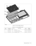
Страница 240: ...Figure 10 1 Top View Major Assemblies 10 4 Replaceable Parts ...
Страница 292: ...Table A 2 Manual Changes by Firmware Version Version Make Manual Changes A 2 Manual Changes ...
Страница 303: ...Change 6 Change the Replaceable Parts as following Figure A 10 Top View Major Assemblies Manual Changes A 13 ...
Страница 308: ......
Страница 311: ...Figure B 1 Power Cable Supplied Power Requirement B 3 ...
Страница 312: ......
Страница 342: ......


