System Setup
9
-
291
NOTICE
When the safety logic circuit file is loaded, the file is not transferred to the safety circuit
board. Select {WRITE} on the safety logic circuit window, and the file is written in the FLASH
ROM of the safety circuit board. After the writing, the file is executed
9.26.17 Initializing the safety logic circuit file
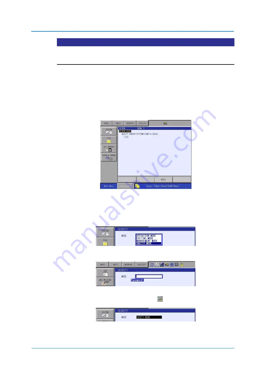
If the following alarm shown below appears when starting the YRC1000, it will become the
MANAGEMENT mode. The alarm occurs when the file does not match the file written in the
FLASH ROM of the safety circuit board. For example, if the safety circuit board is replaced
the spared part, the alarm will occur.
When the alarm occurs, perform the following procedures to restore.
9.26.17.1 Initializing the safety logic circuit file
1. Displaying the window.
Select {SEECURITY} from {SYSTEM} in the main menu.
2. Changing to the SAFETY mode.
Enter the password for the SAFETY mode, and press {ENTER}.
3. When the entered password is correct, the mode is changed to {SAFETY MODE}.
After changing to the SAFETY mode, the icon
is displayed on the status area.
Summary of Contents for YRC1000
Page 1: ...ROBOTICS Instructions Robot controller User manual ...
Page 30: ...Supply 3 30 Hood for CEE connector Covers ...
Page 51: ...Connection 5 51 8 Close the YRC1000 door ...
Page 142: ...System Setup 9 142 6 Select YES All data of the interference signal number is deleted ...
Page 174: ...System Setup 9 174 7 Press ENTER The speed is modified ...
Page 219: ...System Setup 9 219 4 Select GRAPH The graph appears 4 5 6 7 8 9 10 1 2 3 ...
Page 453: ...Description of Units and Circuit Boards 15 453 ...


