


System Setup
9
-
264
3. Select {WRITE} and then {CONFIRM} to enable the changed settings.
When the data is updated correctly, the status on the title line is changed from “NOT
DONE” to “DONE”.
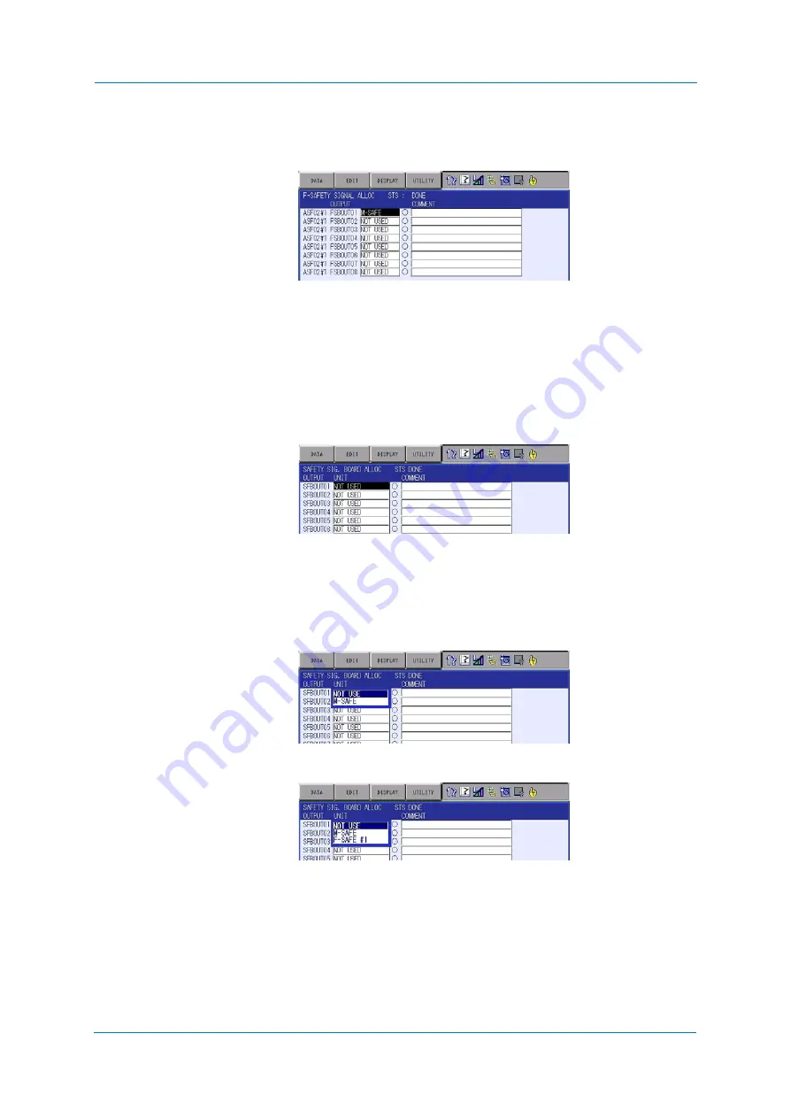
9.26.8
Safety signal board allocation
This window is shown only when the optional safety field bus function is enabled.
1. Select {SAFETY FUNC.}-{SAFETY SIG. BOADR ALLOCATION}.
The marks at the center of the window indicates OFF/ON status.
“
○
” means OFF and the mark “
●
” means ON. Also, comments (up to 32 characters in
one-byte, 16 characters in two-byte) can be input.
2. The initial status is set as “NOT USED”. Press [SELECT] on the programming pendant
and select one of “NOT USED”, “SAFETY LOGIC CIRCUIT” or “FUNCTIONAL
SAFETY”.
When the functional safety (optional) is disabled, the menu of “FUNCTIONAL SAFETY”
is not shown.
<When the functional safety circuit board is disabled>
<When the functional safety circuit board is enabled>
NOT USED
Not available in the safety logic circuit and on the functional
safety.
SAFETY LOGIC CIRCUIT Available in the safety logic circuit.
FUNCTIONLAL SAFETY
Available on the optional functional safety.
Up to eight safety circuit boards can be connected in the
YRC1000. When using a safety circuit board, specify its
board number
Summary of Contents for YRC1000
Page 1: ...ROBOTICS Instructions Robot controller User manual ...
Page 30: ...Supply 3 30 Hood for CEE connector Covers ...
Page 51: ...Connection 5 51 8 Close the YRC1000 door ...
Page 142: ...System Setup 9 142 6 Select YES All data of the interference signal number is deleted ...
Page 174: ...System Setup 9 174 7 Press ENTER The speed is modified ...
Page 219: ...System Setup 9 219 4 Select GRAPH The graph appears 4 5 6 7 8 9 10 1 2 3 ...
Page 453: ...Description of Units and Circuit Boards 15 453 ...


