6.10 Troubleshooting without Fault Display
YASKAWA ELECTRIC
SIEP C710636 02B YASKAWA U1000 Technical Manual
387
T
rou
bl
es
hoot
ing
6
◆
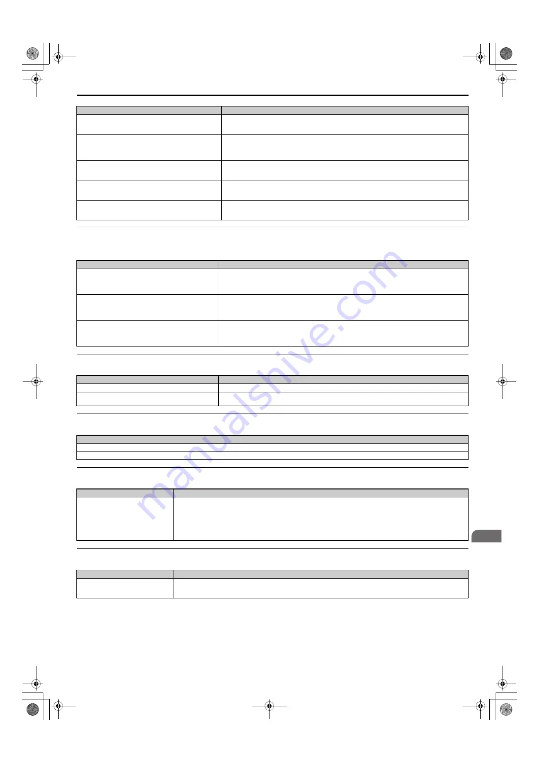
Drive Frequency Reference Differs from the Controller Frequency Reference
Command
◆
Excessive Motor Oscillation and Erratic Rotation
◆
Load Falls When Brake is Applied (Hoist-Type Applications)
◆
Noise From Drive or Motor Cables When the Drive is Powered On
◆
Earth Leakage Circuit Breaker (ELCB) Trips During Run
Although the drive is operating in Open Loop Vector motor control
method, Auto-Tuning has not been performed.
• Perform Auto-Tuning.
• Calculate motor data and reset motor parameters.
• Switch to V/f Control (A1-02 = 0).
Incorrect frequency reference setting.
• Check the multi-function analog input settings. Multi-function analog input terminal A1, A2, or A3 is set for
frequency gain (H3-02, H3-10, or H3-06 is set to “1”), but there is no voltage or current input provided.
• Make sure H3-02, H3-10, and H3-06 are set to the proper values.
• See if the analog input value is set to the right value (U1-13 to U1-15).
The Stall Prevention level during acceleration and deceleration set
too low.
• Check the Stall Prevention level during acceleration (L3-02).
• If L3-02 is set too low, acceleration may be taking too long.
• Increase L3-02.
The Stall Prevention level during run has been set too low.
• Check the Stall Prevention level during run (L3-06).
• If L3-06 is set too low, speed will drop as the drive outputs torque.
• Increase the setting value.
Drive reached the limitations of the V/f motor control method.
• The motor cable may be long enough (over 50 m) to require Auto-Tuning for line-to-line resistance.
• Be aware that V/f Control is comparatively limited when it comes to producing torque at low speeds.
• Consider switching to Open Loop Vector Control.
Cause
Possible Solutions
The analog input gain and bias for the frequency reference input
are set to incorrect values.
• Check the gain and bias settings for the analog inputs that are used to set the frequency reference. Check parameters
H3-03 and H3-04 for input A1, check parameters H3-11, and H3-12 for input A2, and check parameters H3-07 and
H3-08 for input A3.
• Set these parameters to the appropriate values.
A frequency bias signal is being entered via analog input terminals
A1 to A3.
• If more than one of multi-function analog inputs A1 to A3 is set for frequency reference bias (H3-02, H3-10, or H3-06
is set to “0”), then the sum of all signals builds the frequency reference.
• Make sure that H3-02, H3-10, and H3-06 are set appropriately.
• Check the input level set for terminals A1 to A3 (U1-13 to U1-15).
PID control is enabled, and the drive is consequently adjusting the
output frequency to match the PID setpoint. The drive will only
accelerate to the maximum output frequency set in E1-04 while
PID control is active.
If PID control is not necessary for the application, disable it by setting b5-01 to “0”.
Cause
Possible Solutions
Poor balance between motor phases.
Check drive input power voltage to ensure that it provides stable power.
Hunting prevention function is disabled.
• Enable Hunting Prevention (n1-01 = 1).
• Increase the AFR gain (n2-01) or the AFR time constant 1 (n2-02).
Cause
Possible Solutions
The timing for the brake to close and release is not set properly.
Notes on Controlling the Brake when Using the Hoist Application Preset on page 151
.
Insufficient DC Injection Braking.
Increase the amount of DC Injection Braking Current (b2-02).
Cause
Possible Solutions
Relay switching in the drive generates
excessive noise.
• Lower the carrier frequency (C6-02).
• Install a noise filter on the input side of drive input power.
• Install a noise filter on the output side of the drive.
• Place the wiring inside a metal conduit to shield it from switching noise.
• Ground the drive and motor properly.
• Separate the main circuit wiring and the control lines.
• Make sure wires and the motor have been properly grounded.
Cause
Possible Solutions
Excessive leakage current trips ELCB.
• Increase the ELCB sensitivity or use ELCB with a higher threshold.
• Lower the carrier frequency (C6-02).
• Reduce the length of the cable used between the drive and the motor.
Cause
Possible Solutions
SIEP_C710636_02B_1_0.book 387 ページ 2015年11月25日 水曜日 午後4時56分


