3 System Startup
3.5.2 Operation
3-56
3.5.2 Operation
(1) Displays of Tuning Panel Window
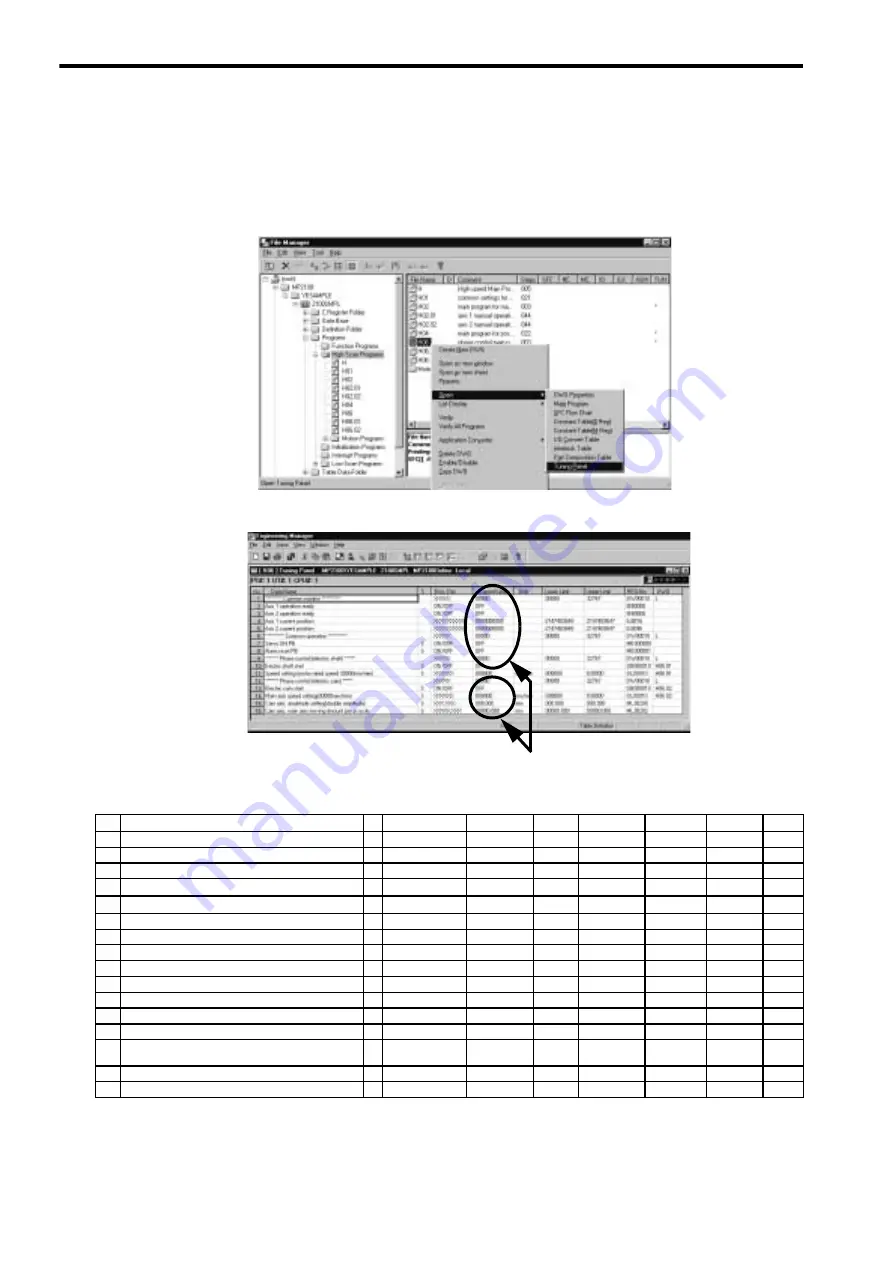
1. Use the Tuning Panel Window for the H06 drawing to check operations, just as described in
3.4.2 Opera-
tion
. Right-click the
H06
drawing in the High Scan Programs Folder and select
Open
–
Tuning Panel
.
2. The drawing Tuning Panel Window for the H06 drawing will be displayed.
The details on the Tuning Panel Window display are shown in the following table.
Input position and current value.
No.
Data Name
S
Display Definition
Current Value
Unit
Lower Limit
Upper Limit
REG-NO.
DWG
1
∗∗∗∗∗∗∗∗∗∗∗∗∗∗∗
Common monitor
∗∗∗∗∗∗∗∗∗∗∗∗∗∗∗
XXXXX
00000
00000
32767
DW00010
L
2
Axis 1 operation ready
ON/OFF
ON
IB80000
3
Axis 2 operation ready
ON/OFF
ON
IB80800
4
Axis 1 current position
XXXXXXXXXX
0000000000
-
2147483648
2147483647
IL8016
5
Axis 2 current position
XXXXXXXXXX
0000000000
-
2147483648
2147483647
IL8096
6
∗∗∗∗∗∗∗∗∗∗∗∗∗∗∗
Common operation
∗∗∗∗∗∗∗∗∗∗∗∗∗∗∗
XXXXX
00000
00000
32767
DW00010
L
7
Servo ON PB
S
ON/OFF
OFF
MB300000
8
Alarm reset PB
S
ON/OFF
OFF
MB300001
9
∗∗∗∗∗∗∗∗∗∗
Phase control (Electronic shaft))
∗∗∗∗∗∗∗∗∗
XXXXX
00000
00000
32767
DW00010
L
10
Electronic shaft start
S
ON/OFF
OFF
DB000010
H06.01
11
Speed setting (motor rated speed: 30000mm/min)
S
XXXXXX
000000
mm/min
-030000
030000
DL00010
H06.02
12
∗∗∗∗∗∗∗∗∗∗
Phase control (Electronic cam)
∗∗∗∗∗∗∗∗∗∗∗
XXXXX
0000
0000
32767
DW00010
L
13
Electronic cam start
S
ON/OFF
OFF
DB000010
H06.02
14
Main axis speed setting
(motor rated speed: 30000 mm/min)
S
XXXXXX
00000
mm/min
00000
030000
DL00010
H06.01
15
Cam axis: amplitude setting (double amplitude)
S
XXX.XXX
010.000
mm
000.000
999.999
ML30200
16
Cam axis: main axis moving amount per cycle
S
XXXXX.XXX
00500.000
mm
00000.000
50000.000
ML30202


