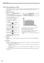
9 Control Block Diagrams
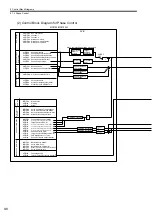
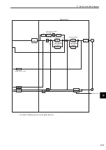
9.1.1 Position Control
9-2
9.1 Motion Control Block Diagrams
9.1.1 Position Control
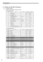
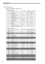
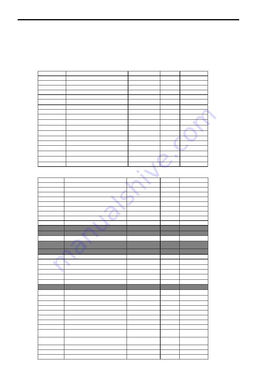
(1) Motion Parameters for Position Control
(a) Fixed Parameters
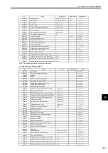
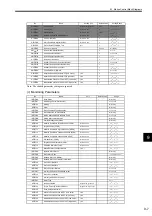
(b) Setting Parameters
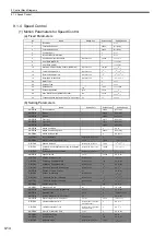
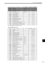
No.
Name
Setting Unit
Default Value
Setting Range
0
Run Mode
−
1
0 to 5
1
Function Selection 1
−
0000 h
Bit Setting
2
Function Selection 2
−
0000 h
Bit Setting
4
Command Unit
−
0
0 to 3
5
Number of Decimal Places
−
3
0 to 5
6
Command Unit per Revolution
Reference unit
10,000
1 to 2
31
−
1
8
Gear Ratio [MOTOR]
−
1
1 to 65,535
9
Gear Ratio [LOAD]
−
1
1 to 65,535
10
Maximum Value of Rotary Counter (POSMAX)
Reference unit
360,000
1 to 2
31
−
1
12
Forward Software Limit
Reference unit
2
31
-1
−
2
31
to 2
31
−
1
14
Reverse Software Limit
Reference unit
-2
31
−
2
31
to 2
31
−
1
16
Backlash Compensation
Reference unit
0
−
2
31
to 2
31
−
1
29
Motor Type
−
0
0 or 1
30
Encoder Type
−
0
0 to 3
34
Rated Speed
min
−
1
3,000
1 to 32,000
36
Encoder Resolution
pulse
65,536
1 to 2
31
−
1
38
Max. Revolutions of Absolute Encoder
Rev
65,534
0 to 2
31
−
1
42
Feedback Speed Moving Average Time Constant
ms
10
0 to 32
No.
Name
Setting Unit
Default Value
Setting Range
OW
00
Run Commands
−
0000 h
Bit Setting
OW
01
Mode 1
−
0000 h
Bit Setting
OW
02
Mode 2
−
0000 h
Bit Setting
OW
03
Function 1
−
0011 h
Bit Setting
OW
04
Function 2
−
0033 h
Bit Setting
OW
05
Function 3
−
0000 h
Bit Setting
OW
08
Motion Command
−
0
0 to 26
OW
09
Motion Command Options
−
0000 h
Bit Setting
OW
0A
Motion Subcommand
−
0
0 to 65,535
OL
0C
Torque Reference
Depends on torque unit.
0
−
2
31
to 2
31
−
1
OW
0E
Speed Limit at Torque Reference
0.01%
15,000
−
32768 to 32,767
OL
10
Speed Reference
Depends on speed unit.
3000
−
2
31
to 2
31
−
1
OL
14
Positive Side Limiting Torque Setting at the Speed
Reference
Depends on torque unit.
30,000
−
2
31
to 2
31
−
1
OL
16
Secondly Speed Compensation
Depends on speed unit.
0
−
2
3
to 2
31
−
1
OW
18
Speed Override
0.01%
10,000
0 to 32767
OL
1C
Position Reference Type
Reference unit
0
−
2
31
to 2
31
−
1
OL
1E
Positioning Completed Width
Reference unit
100
0 to 65,535
OL
20
Positioning Completed Width 2
Reference unit
0
0 to 65,535
OL
22
Deviation Abnormal Detection Value
Reference unit
2
31
−
1
0 to 2
31
−
1
OW
26
Position Complete Timeout
ms
0
0 to 65,535
OL
28
Phase Compensation
Reference unit
0
−
2
31
to 2
31
−
1
OL
2A
Latch zone lower limit (for external positioning)
Reference unit
−
2
31
−
2
31
to 2
31
−
1
OL
2C
Latch zone upper limit (for external positioning)
Reference unit
2
31
−
1
−
2
31
to 2
31
−
1
OW
2E
Position Loop Gain
0.1/s
300
0 to 32,767
OW
2F
Speed Loop Gain
Hz
40
1 to 2,000
OW
30
Speed Feed Forward Compensation
0.01%
0
0 to 32,767
OW
31
Speed Amends
0.01%
0
−
32,768 to 32,767
OW
32
Position Integration Time Constant
ms
0
0 to 32,767
OW
34
Speed Integration Time Constant
0.01 ms
2,000
15 to 65,535
OL
36
Linear Acceleration Time
Depends on acceleration/
deceleration unit.
0
0 to 2
31
-1
OL
38
Linear Deceleration Time
Depends on acceleration/
deceleration unit.
0
0 to 2
31
−
1
OW
3A
S-Curve Acceleration Time
0.1 ms
0
0 to 65,535
OW
3C
Home Return Type
−
0
0 to 19
OW
3D
Home Window
Reference unit
100
0 to 65,535


