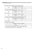
7.2 Motion Parameter Details
7-33
7
IL
04
(cont.)
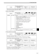
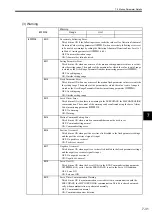
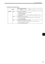
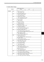
Bit 8
Excessive Speed
This bit turns ON when a speed is set that exceeds the setting range for the speed refer-
ence.
OFF: Speed normal
ON: Excessive speed
Bit 9
Excessively Following Error
This bit turns ON if the following error exceeds the value set for the Deviation Abnor-
mal Detection Value (setting parameter OL
22) when an Excessively Following
Error is set to be treated as an alarm by setting the Deviation Abnormal Detection
Error Level to 0 in Mode 1 (setting parameter OW
01, bit 0).
OFF: In normal deviation range
ON: Abnormal deviation detected
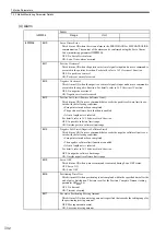
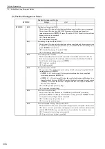
Bit 10
Filter Type Change Error
This bit turns ON if the filter type is changed when the pulses are still distributing.
OFF: No change error
ON: Change error occurred
Bit 11
Filter Time Constant Change Error
This bit turns ON if the filter time constant is changed while the pulses are still distrib-
uting.
OFF: No change error
ON: Change error occurred
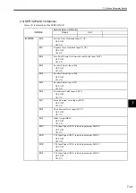
Bit 13
Zero Point Not Set
This bit turns ON if a move command (except for JOG or STEP) is performed when an
infinite length axis is set and the zero point has not been set.
OFF: Zero point set
ON: Zero point not set error
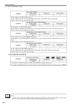
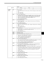
Bit 14
Reserved by system.
Bit 15
Reserved by system.
Bit 16
Servo Driver Synchronization Communication Error
This bit turns ON if a synchronization communication error is detected with the SER-
VOPACK for MECHATROLINK communication.
OFF: No synchronization communication error
ON: Synchronization communication error
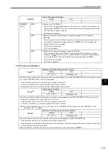
Bit 17
Servo Driver Communication Error
This bit turns ON if two communication errors are detected consecutively in communi-
cation with the SERVOPACK for MECHATROLINK communication.
OFF: No consecutive synchronization communication error
ON: Consecutive synchronization communication errors
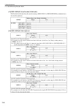
Bit 18
Servo Driver Command Timeout Error
This bit turns ON if a command sent to the SERVOPACK for MECHATROLINK
communication is not completed within a specific amount of time.
Bit 19
ABS Encoder Count Exceeded
This bit turns ON if the number of turns from the absolute encoder exceeds the range
that the MP2100 Module can handle. This parameter is valid when using an absolute
encoder and a finite-length axis. This bit also turns ON if the result of the operation
converting the current position to reference units when the power is turned ON
exceeds 32 bits.
OFF: In count range
ON: Outside count range
Bit 30
SERVOPACK Motor Type Mismatch
OFF: Motor type matches
ON: Motor type does not match
Bit 31
SERVOPACK Encoder Type Mismatch
OFF: Encoder type matches
ON: Encoder type does not match
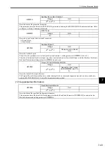
IL
04
Alarm
Range
Unit
−
−

