


Ala
rm L
ist
Ala
rm
Numb
er
(
1
00
0 to
19
99)
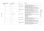
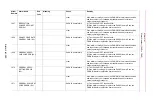
Alarm List-356
YSF25 board failure
(1)Turn the power OFF then back ON.
(2)If the alarm occurs again, replace the YSF25 board. Save the
CMOS.BIN before replace the board to be safe.
other
If the alarm occurs again, save the CMOS.BIN in maintenance mode,
and then contact your Yaskawa representative about occurrence
status (operating procedure).
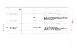
1645
F-SAFE CRC ERROR
Sub Code: Signifies the file
kind in which the alarm
occurred.
YSF25 board failure
(1)Turn the power OFF then back ON.
(2)If the alarm occurs again, replace the YSF25 board. Save the
CMOS.BIN before replace the board to be safe.
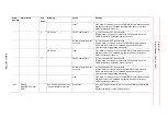
YIF01 board failure
(1)Turn the power OFF then back ON.
(2)If the alarm occurs again, replace the YIF01 board. Save the
CMOS.BIN before replace the board to be safe. Replace the YIF01
board, and then load the CMOS.BIN saved before alarm occurred.
other
If the alarm occurs again, save the CMOS.BIN in maintenance mode,
and then contact your Yaskawa representative about occurrence
status (operating procedure).
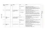
1646
F-SAFE
COMM.SETTING
ERROR
Sub Code: The rotary switch
number recorded in the
YSF25 board is shown.
Setting error
(1)Select the following menu.
∙
[File] - [Initialize], [Functional Safety Board FLASH Reset] in
maintenance mode.
(2)Turn the power OFF then back ON.
Setting error
Confirm that the rotary switch on the YSF25[#1-8] board is set to [0-7].
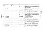
YSF25 board failure
(1)Turn the power OFF then back ON.
(2)If the alarm occurs again, replace the YSF25 board. Save the
CMOS.BIN before replace the board to be safe.
other
If the alarm occurs again, save the CMOS.BIN in maintenance mode,
and then contact your Yaskawa representative about occurrence
status (operating procedure).
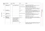
1649
MODE SIGNAL
ERROR
Detect mode signal error
Connection failure
(1)Turn the power OFF then back ON.
(2) If the alarm occurs again, check the connection and insertion of the
following cables and connectors.
∙
Programming Pendant cable
∙
X81 cable (Cable in the robot controller)
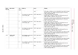
Alarm
Number
Alarm Name
Sub
Code
Meaning
Cause
Remedy


