YASKAWA
TOEPYAIHV6002A HV600 Drive Programming
493
■
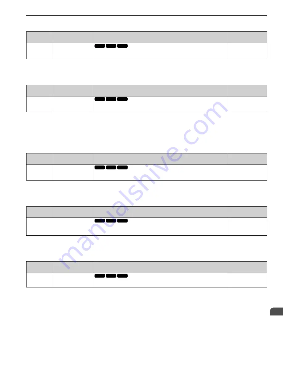
Y9-33: Lag Follower Decel Activ Time
No.
(Hex.)
Name
Description
Default
(Range)
Y9-33
(3E14)
RUN
Lag Follower Decel Activ
Time
Sets the time during which the deceleration time set in
Y9-32 [Lag Follower Deceleration Rate]
is
effective. The drive will use the standard deceleration rate when it is expired.
0.0 s
(0.0 - 3600.0 s)
Note:
Set this parameter to 0.0 to disable the function.
■
Y9-34: Low Feedback De-stage
No.
(Hex.)
Name
Description
Default
(Range)
Y9-34
(3E15)
RUN
Low Feedback De-stage
Sets the low feedback level that will trigger a quick de-stage.
0.00
(0.00 - 600.00)
Note:
•
Parameters
b5-46 [PID Unit Display Selection]
,
b5-38 [PID User Unit Display Scaling]
, and
b5-39 [PID User Unit Display Digits]
set the
unit, range, and resolution.
•
The quick de-stage ignores
Y9-12 [De-staging Mode]
and
Y9-15 [De-staging Delay Time]
and only uses an internal 2 s delay.
•
Set this parameter to 0.00 to disable the function.
■
Y9-35: Alternation Stabilize Time
No.
(Hex.)
Name
Description
Default
(Range)
Y9-35
(3E16)
RUN
Alternation Stabilize Time
Sets the maximum length of time the drive will stay running after it is called to alternate-out. The
drive will be in Alternation Stabilization Mode during this time.
0 s
(0 - 1000 s)
Note:
Set this parameter to 0 to disable the function.
■
Y9-36: Alternation Stabilize Bias
No.
(Hex.)
Name
Description
Default
(Range)
Y9-36
(3E17)
RUN
Alternation Stabilize Bias
Sets the minimum quantity of PID error applied to the drive during Alternation Stabilization Mode. A
lower value can cause it to stay running longer, while a higher value will make the change faster, but
it will have a larger pressure change.
0.50%
(0.00 - 10.00%)
Note:
Set as a percentage of
b5-38 [PID Unit Scaling]
.
■
Y9-50: PI Auxiliary Control Source
No.
(Hex.)
Name
Description
Default
(Range)
Y9-50
(3E25)
PI Auxiliary Control Source
Sets the signal to use for
PI Auxiliary Control [YF-xx]
when
Y1-01 = 3 [Multiplex Mode = Memobus
Network]
.
0
(0 - 3)
Note:
•
Drives that have
YF-19 = 0 [PI Aux Ctrl Feedback WireBreak = Disabled]
and
Y9-50 ≠ 3
will have wire-break detection and will
continuously send valid or invalid PI Aux Feedback signals to the Network.
•
When
YF-19 = 2 [Fault (no retry, coast to stop)]
and
Y9-50 ≠ 3
, the PI Auxiliary Feedback detection will cause an alarm(not a fault) when
one of these conditions is true:
–
The drive is in HAND Mode
–
There is no Lead Drive on the network
–
The drive is not in AUTO Mode
0 : Analog Only
V/f
OLV/PM
OLV/PM
EZOLV
V/f
OLV/PM
OLV/PM
EZOLV
V/f
OLV/PM
OLV/PM
EZOLV
V/f
OLV/PM
OLV/PM
EZOLV
V/f
OLV/PM
OLV/PM
EZOLV


