YASKAWA
TOEPYAIHV6002A HV600 Drive Programming
377
Note:
The drive applies a hysteresis of approximately 10% of the drive rated output current or the motor rated torque to the overtorque/
undertorque/underload detection function.
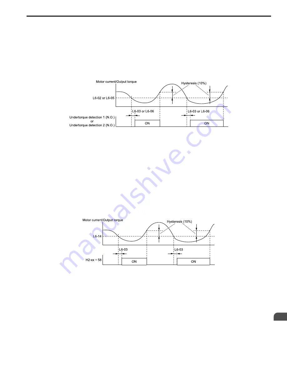
Undertorque Detection Time Chart
When you use Overtorque/Undertorque Detection 1, the drive detects undertorque if the motor current or motor
torque is less than or equal to the detection level set in
L6-02
for the time set in
L6-03
. Parameter
L6-01
sets the
operation after detection.
When you use Overtorque/Undertorque Detection 2, set the operation in
L6-04, L6-05, and L6-06
.
Use
H2-01 to H2-03 [MFDO Function Selection]
to set the terminal that outputs the alarm.
L6-02:
L6-03:
L6-05:
L6-06:
Figure 2.103 Time Chart for Undertorque Detection
Note:
The drive applies a hysteresis of approximately 10% of the drive rated output current or the motor rated torque to the overtorque/
undertorque/underload detection function.
Underload Detection Time Chart
When
L6-01 = 9 [UL6 @ Speed Agree - Alarm only] to 12 [UL6 @ RUN - Fault]
, the drive will detect underload if
the motor current or output torque is less than or equal to the detection level for the time set in
L6-03
.
Note:
The linear curve of
L6-02
,
L6-13 [Motor Underload Curve Select]
, and
L6-14 [Motor Underload Level @ Min Freq]
sets the underload
detection level.
Use
H2-01 to H2-03 [MFDO Function Selection]
to set the terminal that outputs the alarm.
H2-xx = 58:
L6-03:
L6-14:
Figure 2.104 Time Chart for Underload Detection at Minimum Frequency
Note:
The drive applies a hysteresis of approximately 10% of the drive rated output current or the motor rated torque to the overtorque/
undertorque/underload detection function.


