HYDRAULIC SYSTEM
L4100, WSM
8-S18
(EU)
Bushings
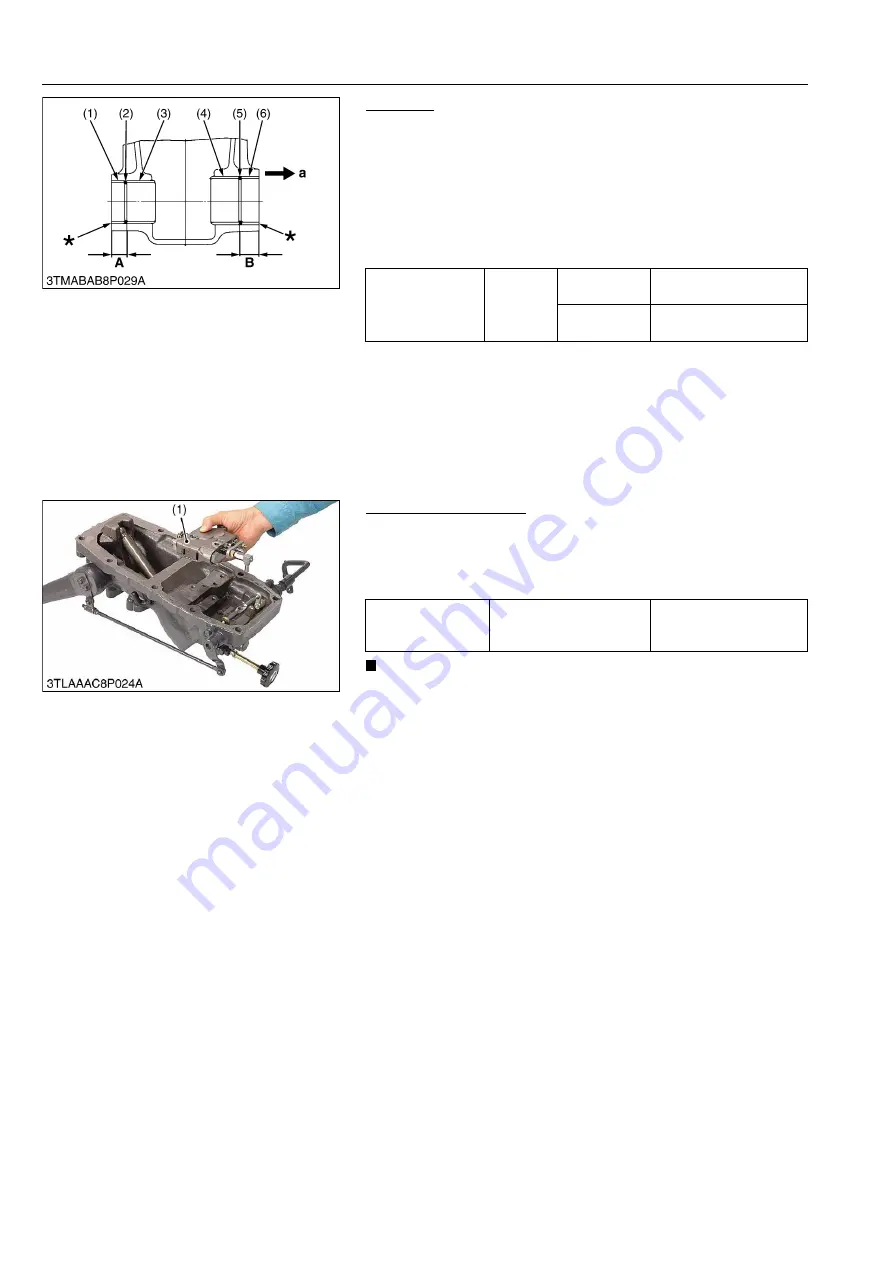
1. Remove the bushings (3) and (4).
(When reassembling)
• When press-fitting new bushings (3), (4) with a press-fitting tool
(See page G-44) observe the dimensions described in the
figure.
• Apply transmission fluid to the hydraulic cylinder boss and
bushing.
• Press-fit the bushing so that each seam face upward.
9Y1210278HYS0039US0
(3) Position Control Valve
Position Control Valve
1. Loosen and remove the position control valve mounting screws.
2. Take out the position control valve (1).
(When reassembling)
• Take care not to damage the O-rings.
IMPORTANT
• Measure the distance between the spool edge and spool
joint 2 edge before disassembling.
9Y1210278HYS0022US0
Press-fit location of
bushings
Factory
specifica-
tion
"A"
(Left side)
20.0 to 21.0 mm
0.788 to 0.826 in.
"B"
(Right side)
18.0 to 19.0 mm
0.709 to 0.748 in.
(1) Collar (Left)
(2) O-ring
(3) Bushing (Left)
(4) Bushing
(5) O-ring
(6) Collar (Right)
a: Right Side *
b: Flush the end of collar with the
end of hydraulic cylinder body.
A: Left
Length
B: Right
Length
Tightening torque
Position control valve
mounting screw
24 to 27 N·m
2.4 to 2.8 kgf·m
18 to 20 lbf·ft
(1) Position Control Valve
KiSC issued 08, 2012 A
Summary of Contents for Kubota L4100
Page 1: ...L4100 WORKSHOP MANUAL TRACTOR KiSC issued 08 2012 A...
Page 3: ...I INFORMATION KiSC issued 08 2012 A...
Page 9: ...INFORMATION L4100 WSM I 5 EU 9Y1210278INI0002US0 KiSC issued 08 2012 A...
Page 13: ...INFORMATION L4100 WSM I 9 EU Mid mount type ROPS 9Y1210278INI0006US0 KiSC issued 08 2012 A...
Page 14: ...G GENERAL KiSC issued 08 2012 A...
Page 67: ...1 ENGINE KiSC issued 08 2012 A...
Page 130: ...2 CLUTCH KiSC issued 08 2012 A...
Page 160: ...3 TRANSMISSION KiSC issued 08 2012 A...
Page 161: ...CONTENTS 1 STRUCTURE 3 M1 MECHANISM KiSC issued 08 2012 A...
Page 201: ...4 REAR AXLE KiSC issued 08 2012 A...
Page 202: ...CONTENTS 1 STRUCTURE 4 M1 MECHANISM KiSC issued 08 2012 A...
Page 210: ...5 BRAKES KiSC issued 08 2012 A...
Page 211: ...CONTENTS 1 STRUCTURE 5 M1 2 OPERATION 5 M2 MECHANISM KiSC issued 08 2012 A...
Page 224: ...6 FRONT AXLE KiSC issued 08 2012 A...
Page 225: ...CONTENTS 1 STRUCTURE 6 M1 2 FRONT WHEEL ALIGNMENT 6 M2 MECHANISM KiSC issued 08 2012 A...
Page 245: ...7 STEERING KiSC issued 08 2012 A...
Page 264: ...8 HYDRAULIC SYSTEM KiSC issued 08 2012 A...


