HYDRAULIC SYSTEM
L4100, WSM
8-S19
(EU)
9Y1210278HYS0023US0
IMPORTANT
• Set screw (3) and spool joint 1 (2) are adjusted to very close
accuracy. Do not disassemble them unless necessary.
If disassembled due to unavoidable reasons, be sure to
make the following adjustments before assembling.
Q
Spool joint 1 (2)
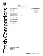
1. Turn and adjust the spool joint 1 (2) so that dimension
"a"
between the spool joint 2 (1) and the plate 1 (4) is 48.0 mm
(1.89 in.).
2. After the adjustment, be sure to adjust the position control
feedback rod.
Q
Set Screw (3)
1. Set the dimension
"b"
between the plate 1 (4) and the valve
body to 15.0 mm (0.591 in.).
2. Turn and adjust the set screw (3) so that the clearance
"c"
between the set screw (3) and the poppet 2 (5) becomes 0.1 to
0.2 mm (0.0039 to 0.0079 in.).
(When reassembling)
9Y1210278HYS0040US0
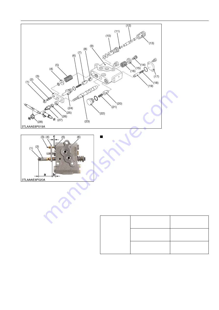
(1) Nut 1
(2) Set Screw
(3) Plate 1
(4) Washer
(5) Spring
(6) Spring
(7) Poppet 1
(8) Valve Seat
(9) Valve Body
(10) Sleeve
(11) Backup Ring
(12) Poppet 2
(13) Plug 1
(14) Screw
(15) Spring Holder
(16) Spring
(17) Plate 2
(18) Spring
(19) Poppet 3
(20) Unload Poppet
(21) Spring
(22) Unload Plug
(23) Spool
(24) Plug 2
(25) Nut
(26) Lock Nut
(27) Spool Joint 1
(28) Spool Joint 2
Tightening torque
Position control valve seat
plug 1
40 to 58 N·m
4.0 to 6.0 kgf·m
29 to 43 lbf·ft
Position control valve seat
plug 2
30 to 49 N·m
3.0 to 5.0 kgf·m
22 to 36 lbf·ft
Position control valve
unload plug
40 to 58 N·m
4.0 to 6.0 kgf·m
29 to 43 lbf·ft
(1) Spool Joint 2
(2) Spool Joint 1
(3) Set Screw
(4) Plate 1
(5) Poppet 2
(6) Valve Body
a: Dimension
b: Dimension
c: Clearance
KiSC issued 08, 2012 A
Summary of Contents for Kubota L4100
Page 1: ...L4100 WORKSHOP MANUAL TRACTOR KiSC issued 08 2012 A...
Page 3: ...I INFORMATION KiSC issued 08 2012 A...
Page 9: ...INFORMATION L4100 WSM I 5 EU 9Y1210278INI0002US0 KiSC issued 08 2012 A...
Page 13: ...INFORMATION L4100 WSM I 9 EU Mid mount type ROPS 9Y1210278INI0006US0 KiSC issued 08 2012 A...
Page 14: ...G GENERAL KiSC issued 08 2012 A...
Page 67: ...1 ENGINE KiSC issued 08 2012 A...
Page 130: ...2 CLUTCH KiSC issued 08 2012 A...
Page 160: ...3 TRANSMISSION KiSC issued 08 2012 A...
Page 161: ...CONTENTS 1 STRUCTURE 3 M1 MECHANISM KiSC issued 08 2012 A...
Page 201: ...4 REAR AXLE KiSC issued 08 2012 A...
Page 202: ...CONTENTS 1 STRUCTURE 4 M1 MECHANISM KiSC issued 08 2012 A...
Page 210: ...5 BRAKES KiSC issued 08 2012 A...
Page 211: ...CONTENTS 1 STRUCTURE 5 M1 2 OPERATION 5 M2 MECHANISM KiSC issued 08 2012 A...
Page 224: ...6 FRONT AXLE KiSC issued 08 2012 A...
Page 225: ...CONTENTS 1 STRUCTURE 6 M1 2 FRONT WHEEL ALIGNMENT 6 M2 MECHANISM KiSC issued 08 2012 A...
Page 245: ...7 STEERING KiSC issued 08 2012 A...
Page 264: ...8 HYDRAULIC SYSTEM KiSC issued 08 2012 A...


