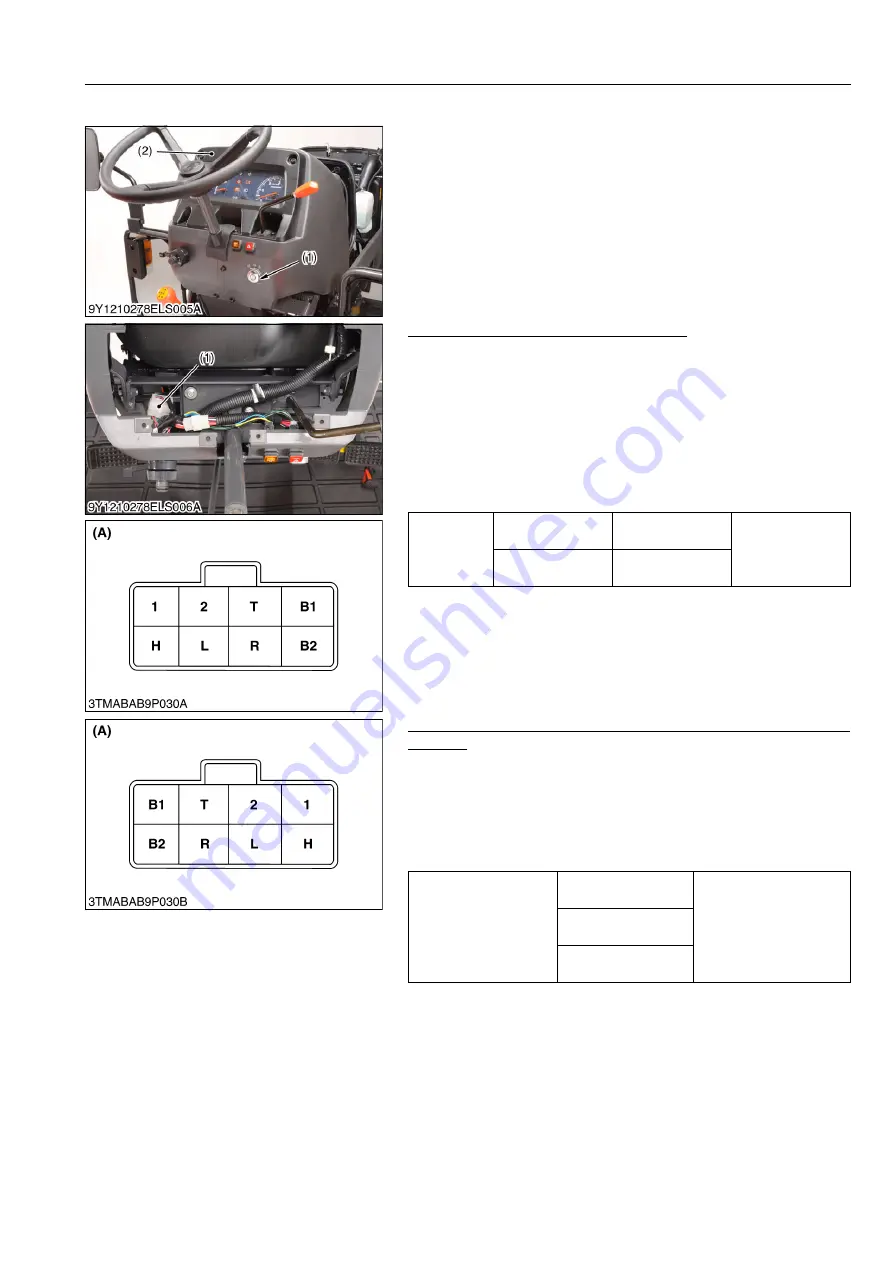
ELECTRICAL SYSTEM
L4100, WSM
9-S17
(EU)
(9) Combination Switch
1. Turn off the main switch (1).
2. Remove the panel board (2).
3. Perform the following checkings.
9Y1210278ELS0014US0
Connector Voltage (Wire Harness Side)
1. Disconnect the
8P
connector (1) from the combination switch.
2. Measure the voltage with a voltmeter across the connector
B1
terminal and chassis when the main switch is
OFF
position.
3. If the voltage differs from the battery voltage, the wiring harness
is faulty.
4. Measure the voltage with a voltmeter across the connector
B2
terminal and chassis when the main switch is
ON
position.
5. If the voltage differs from the battery voltage, check the wiring
harness and main switch.
9Y1210278ELS0015US0
Head Light Switch Continuity when Setting Switch at OFF
Position
1. Disconnect the
8P
connector from the combination switch.
2. Set the light switch to the
OFF
position.
3. Measure the resistance with an ohmmeter across the
B1
terminal to the
T
terminal, the
B1
terminal to the
1
terminal and
the
B1
terminal to the
2
terminal.
4. If infinity is not indicated, renew the switch.
WSM000001ELS0015US0
(1) Main Switch
(2) Panel Board
Voltage
Main switch at
OFF
position
B1
terminal –
Chassis
Battery voltage
Main switch at
ON
position
B2
terminal –
Chassis
(1)
8P
Connector
(A) 8P Connector
(Wire Harness Side)
Resistance (Switch at
OFF
position)
B1
terminal –
T
terminal
Infinity
B1
terminal –
1
terminal
B1
terminal –
2
terminal
(A) Combination Switch Side 8P
Connector
KiSC issued 08, 2012 A
Summary of Contents for Kubota L4100
Page 1: ...L4100 WORKSHOP MANUAL TRACTOR KiSC issued 08 2012 A...
Page 3: ...I INFORMATION KiSC issued 08 2012 A...
Page 9: ...INFORMATION L4100 WSM I 5 EU 9Y1210278INI0002US0 KiSC issued 08 2012 A...
Page 13: ...INFORMATION L4100 WSM I 9 EU Mid mount type ROPS 9Y1210278INI0006US0 KiSC issued 08 2012 A...
Page 14: ...G GENERAL KiSC issued 08 2012 A...
Page 67: ...1 ENGINE KiSC issued 08 2012 A...
Page 130: ...2 CLUTCH KiSC issued 08 2012 A...
Page 160: ...3 TRANSMISSION KiSC issued 08 2012 A...
Page 161: ...CONTENTS 1 STRUCTURE 3 M1 MECHANISM KiSC issued 08 2012 A...
Page 201: ...4 REAR AXLE KiSC issued 08 2012 A...
Page 202: ...CONTENTS 1 STRUCTURE 4 M1 MECHANISM KiSC issued 08 2012 A...
Page 210: ...5 BRAKES KiSC issued 08 2012 A...
Page 211: ...CONTENTS 1 STRUCTURE 5 M1 2 OPERATION 5 M2 MECHANISM KiSC issued 08 2012 A...
Page 224: ...6 FRONT AXLE KiSC issued 08 2012 A...
Page 225: ...CONTENTS 1 STRUCTURE 6 M1 2 FRONT WHEEL ALIGNMENT 6 M2 MECHANISM KiSC issued 08 2012 A...
Page 245: ...7 STEERING KiSC issued 08 2012 A...
Page 264: ...8 HYDRAULIC SYSTEM KiSC issued 08 2012 A...


