


86
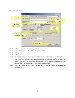
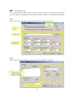
There are following kind of inverter tags (select from Register/Coil Type of Add Tag window).
This page is described based on VF-S11. Kind and number of parameter is different depending on the model of
inverters. And, some parameters cannot change while inverter is RUN, or it becomes effective after rebooting
of inverter. Refer the communication manual and instruction manual of the inverter.
VF- S11 and VF-nC1has no serial communication port. If you use these, communication option is required
(For S11 : RS4003Z, for nC1 : RS4001Z/4002Z).
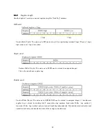
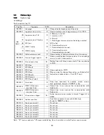
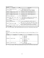
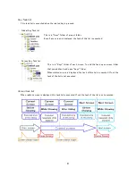
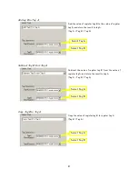
Run/Stop bit, Fwd/Rev bit, Jog bit, Trip Reset bit
These bit can used for monitoring only.
Operation frequency, Monitoring Frequency
To set output frequency, set frequency value to “Operation frequency”. To monitor current output frequency,
refer “Monitoring Frequency” (This is read only tag). When the INV is trip, the output frequency just before the
trip is stored.
Data format is “XXX.XX” in Hz. If you drive INV in 60.00Hz, set the value of 6000. Frequency setting is enabled
only case of “Fmod” is set to “RS485 Serial communication”. Actual output frequency is limited by the
parameter “FH”, “UL”, “LL” of INV.
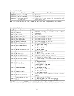
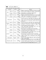
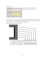
Data registers
This is not available.
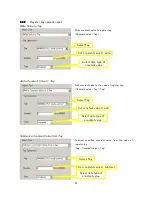
Basic Parameters, I/O Parameters, Frequency Parameters, Drive mode Parameters, Torque
Performance, Accel/Decel Time Parameters, Protection Parameters, Panel Parameters,
Communication parameters, Reservation Area parameters
These are extended parameter. Communication number of each parameter corresponds to tag number. Put “A”
ahead of the communication number, then it becomes the tag number of Inverter tag. For example, basic
parameter “Acc” becomes “A0009”, extended parameter “F100” becomes “A0100”.
When you use these tags, set value is only written to RAM area of INV. Set value is lost when the power of INV
is turned OFF. The INV is operated in previous parameters after rebooting.
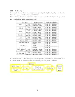
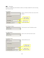
Command Parameters
Command parameters for serial communication. You can control INV, output terminal of INV, and 7segment LED
of INV front panel as output of PMIU unit. Refer serial communication manual of the INV.
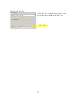
Code parameters
Only AFC00, AFC01 is available. Refer serial communication manual of the INV.
Summary of Contents for TR PMIU
Page 11: ...1 Chapter Chapter Chapter Chapter 1 1 1 1 Introduction Introduction Introduction Introduction ...
Page 15: ...5 Chapter 2 Chapter 2 Chapter 2 Chapter 2 Hardware Hardware Hardware Hardware ...
Page 23: ...13 Input Wiring for TR PDIO0808 P Output ...
Page 24: ...14 Wiring for TR PDIO0808 N Input Output ...
Page 26: ...16 Input Input Wiring for TR PDIX1600 ...
Page 28: ...18 Output Wiring for TRSDOX0016N ...
Page 39: ...29 Chapter Chapter Chapter Chapter 3 3 3 3 TR PGMS TR PGMS TR PGMS TR PGMS ...
Page 83: ...73 Chapter 5 Chapter 5 Chapter 5 Chapter 5 Tag Tag Tag Tag ...
Page 98: ...88 Chapter Chapter Chapter Chapter 6 6 6 6 Task Task Task Task ...
Page 124: ...114 Chapter 8 Chapter 8 Chapter 8 Chapter 8 Screen Screen Screen Screen ...
Page 167: ...157 Note for the numbers of alarm message ...
Page 176: ...166 Appendix Appendix Appendix Appendix ...
Page 181: ...171 ...
Page 182: ...172 ...