


81
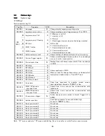
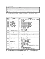
System register tag 2/2
Tag No.
Tag name
R/W
Description
SW 0125
Factory reserved 8
R
Do not use.
SW 0126
Factory reserved 9
R
Do not use.
SW 0127
Failed expansion slot
reconnect time
R
Shows
time
in
sec
recover
the
communication
with
Expansion I/O units.
Note : “R” means read only, “W” means writable tag. Do not use (refer or write) Factory reserved area.
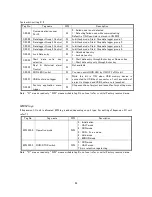
System bit/coil tag 1/2
Tag No.
Tag name
R/W
Description
S 0000
Carry bit
W
ON/OFF
according
to
operation
result
of
ladder
instruction.
S 0001
Not available
R
Not available
S 0003
Minute change pulse
R
It is turned ON/OFF every minute.
S 0004
Hour change pulse
R
It is turned ON/OFF every hour.
S 0005
Day change pulse
R
It is turned ON/OFF every day.
S 0006
Month change pulse
R
It is turned ON/OFF every month.
S 0007
Year change pulse
R
It is turned ON/OFF every year.
S 0008
Screen saver control
W
0 : Screen saver disable
1 : Screen saver enable.
S 0009
Beeper (Buzzer) ON/OFF
W
0 : Beeper disable
1 : Beeper enable.
This can change in RUN.
S 0010
Battery status
W
0 : Battery OK
1 : Battery voltage is low (below 2.2V).
S 0012
Update Historical trend
W
Update Historical trend object on screen.
S 0014
Acknowledge all alarms
R
0 : All alarms are acknowledged
1 : Unacknowledged alarm is exist in Real time/Historical
alarm.
S 0016
Valid key Beeper
W
0 : valid beeper enable
1 : valid beeper disable
This can change in RUN mode.
S 0017
Invalid key Beeper
W
0 : invalid beeper enable
1 : invalid beeper disable
This can change in RUN mode.
S 0019
Invalid data entry
R
0 : Entry data is valid
1 : Entry data is invalid
S 0020
Popup screen control
W
Trigger of popup screen. Active screen number is stored in
S0023.
S 0021
Communication recover
Port 1
W
0 : Failed node is not detected
1 : Detecting failed node while communicating
Default is ON. Scan time is stored in SW 0018
Note : “R” means read only, “R/W” means writable tag. Do not use (refer or write) Factory reserved area.
Summary of Contents for TR PMIU
Page 11: ...1 Chapter Chapter Chapter Chapter 1 1 1 1 Introduction Introduction Introduction Introduction ...
Page 15: ...5 Chapter 2 Chapter 2 Chapter 2 Chapter 2 Hardware Hardware Hardware Hardware ...
Page 23: ...13 Input Wiring for TR PDIO0808 P Output ...
Page 24: ...14 Wiring for TR PDIO0808 N Input Output ...
Page 26: ...16 Input Input Wiring for TR PDIX1600 ...
Page 28: ...18 Output Wiring for TRSDOX0016N ...
Page 39: ...29 Chapter Chapter Chapter Chapter 3 3 3 3 TR PGMS TR PGMS TR PGMS TR PGMS ...
Page 83: ...73 Chapter 5 Chapter 5 Chapter 5 Chapter 5 Tag Tag Tag Tag ...
Page 98: ...88 Chapter Chapter Chapter Chapter 6 6 6 6 Task Task Task Task ...
Page 124: ...114 Chapter 8 Chapter 8 Chapter 8 Chapter 8 Screen Screen Screen Screen ...
Page 167: ...157 Note for the numbers of alarm message ...
Page 176: ...166 Appendix Appendix Appendix Appendix ...
Page 181: ...171 ...
Page 182: ...172 ...